background image

DLP Projection TV

Installation

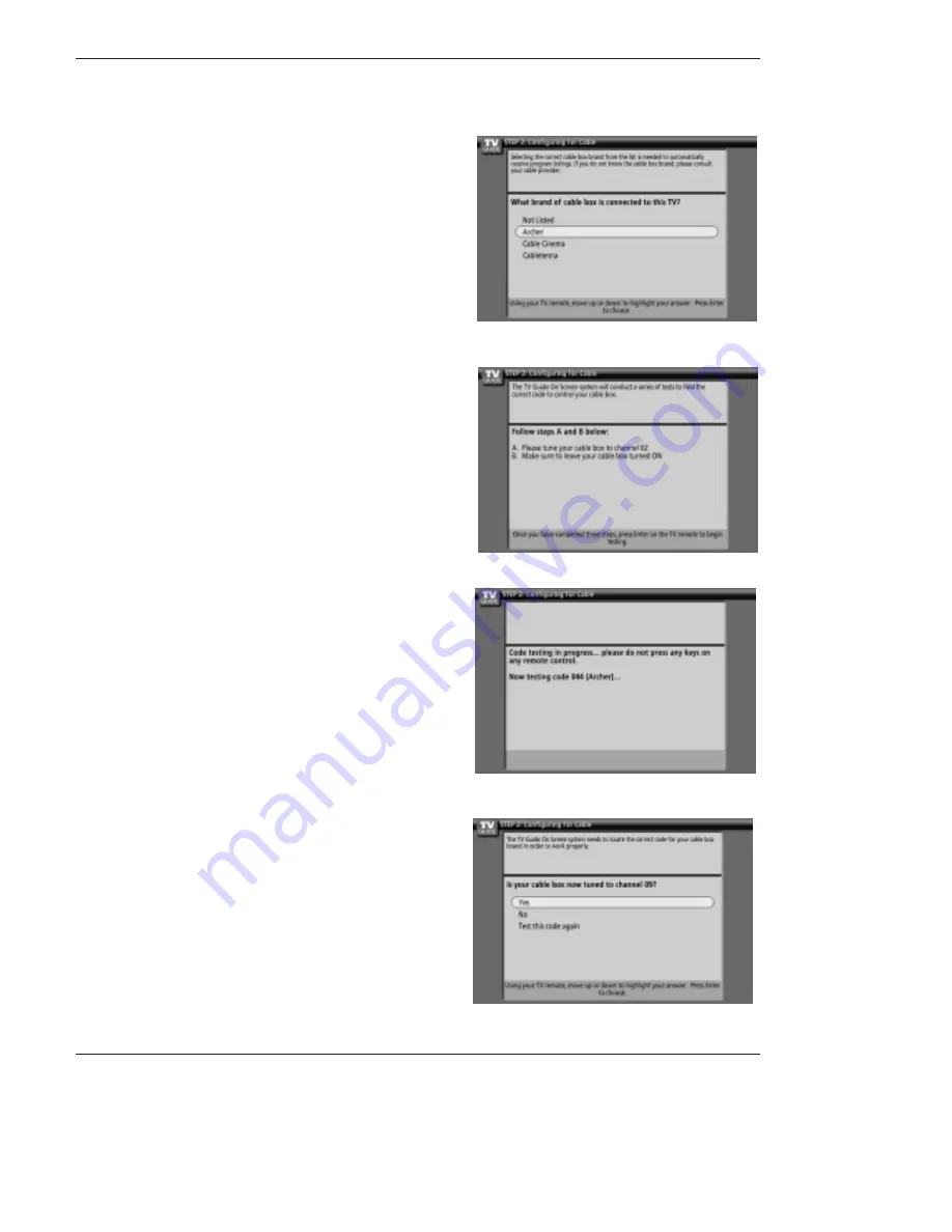
10. Screen 8: Cable Box Brand Name

•Use the 

D

E

buttons to select a cable box brand.

•Press

ENTER

to display Screen 9.

11. Screen 9: Cable Box Preparation

Follow the on-screen instructions, and press 

ENTER

to display

Screen 10.

12. Screen 10: Cable Box Code Testing

When testing is done, Screen 11 displays automatically.

13. Screen 11: Cable Box Tuned to Channel 9?

If you select Yes, you see Screen 12.

If you select No, a different code is tested in Screen 10.

Notes:

Many Cable Boxes require testing more than one code.

If you select Test this code again, the same code is tested again
in Screen 10.

Summary of Contents for DU-52SX4D-UB

Page 1: ...EUT Type 62 DLP Projection TV FCC ID BEJDU62SX40D Test Report No GETEC E3 05 023 FCC Class B Certification APPENDIX H USER S MANUAL ...

Page 2: ...T Please read this manual carefully and completely before operating your TV Retain this manual for future reference Record model number and serial number of the TV in the spaces provided below See the label attached on the back cover and relate this information to your dealer if you require service Model Number Serial Number ...

Page 3: ... and found to comply with the limits for a Class B digital device pursuant to Part 15 of the FCC Rules These limits are designed to provide reasonable protection against harmful interference in a residential installation This equipment generates uses and can radiate radio frequency energy and if not installed and used in accordance with the instructions may cause harmful interference to radio comm...

Page 4: ...system is manufactured under license from Gemstar TV Guide International Inc and or one of its affiliates Digital Cable Compatibility Digital Cable Compatibility This digital television is capable of receiving basic analog digital basic and digital premium cable television programming by direct connection to a cable system providing such programming A security card provided by your cable operator ...

Page 5: ...Follow all instructions 5 Do not use this apparatus near water 6 Clean only with dry cloth 7 Do not block any ventilation openings Install in accordance with the manufacturer s instructions 8 Do not install near any heat sources such as radiators heat registers stoves or other apparatus including ampli fiers that produce heat 9 Do not defeat the safety purpose of the polarized or grounding type pl...

Page 6: ...ets loose or damaged wall outlets extension cords frayed power cords or damaged or cracked wire insulation are dangerous Any of these conditions could result in electric shock or fire Periodically examine the cord of your appliance and if its appearance indicates damage or deterioration unplug it discontinue use of the appliance and have the cord replaced with an exact replacement part by an autho...

Page 7: ...Red flashing There is a problem with the lamp or around it Contact an authorized service center Green flashing The lamp cover is not closed Orange The projection TV is overheating Check the blocked vents of the Projection TV and the accumulated dust in the dust filter Red The projection TV shuts down due to overheating Red flashing The projection TV shuts down check the cooling fan Contact your se...

Page 8: ... Connect to external Dolby Digital Center preamp output VARIABLE AUDIO OUT Used to connect either an external amplifier or add a sub woofer to your surround sound system COMPONENT INPUT 1 2 Connect a component video audio device to these jacks Refer to your DVD manual for further information VIDEO 1 or 2 Connects the video sig nals from various types of equipment Left Right AUDIO Used for stereo s...

Page 9: ...f jacks on the rear jackpack may be connect ed to the front connection panel To use the side jacks as the signal source select them using Main Input menu as described on page 58 They will be named Front Video in the Main Input menu If you input both Front Video and S Video only the S Video will work If you re connecting a video game device make sure to change the picture settings with the EZ Pictu...

Page 10: ...le ANTENNA Multi family Dwellings Apartments Connect to wall antenna socket Single family Dwellings Houses Connect to wall jack for outdoor antenna Outdoor Antenna Wall Antenna Socket VHF Antenna UHF Antenna RF Coaxial Wire 75 ohm Bronze Wire Turn clockwise to tighten Bronze Wire Be careful not to bend the bronze wire when connecting the antenna Bronze Wire Cable TV Wall Jack RF Coaxial Wire 75 oh...

Page 11: ...Right red If you connect an S VIDEO output from VCR to the S VIDEO input the picture quality is improved compared to connecting a regular VCR to the Video input 2 Insert a video tape into the VCR and press PLAY on the VCR Refer to the VCR owner s manual 3 Select the input source with using the TV VIDEO button on the remote control Note that this TV finds the connected input sources automatically f...

Page 12: ... MONITOR OUTPUT VIDEO INPUT2 VIDEO INPUT1 DIGITAL AUDIO OPTICAL INPUT1 COMPONENT2 DIGITAL AUDIO OPTICAL INPUT2 DVI IEEE1394 DIGITAL AUDIO OPTICAL OUTPUT ANTENNA C A B L E C A R D DVI VARIABLE AUDIO OUT G LINK HDMI UPGRADE PORT R AUDIO L S VIDEO B R R AUDIO L DIGITAL AUDIO OPTICAL DVD Notes Digital Audio will not work for Component 1 input source Digital Audio operation has priority if Digital Audi...

Page 13: ...he digital set top box 2 Use TV VIDEO on the remote control to select Component 1 Component 2 RGB DTV or HDMI DVI source HDSTB Setup HDSTB Setup This TV can receive Digital Over the air Cable signals without an external digital set top box However if you do receive Digital signals from a digital set top box or other digital external device refer to the figure as shown below This TV supports HDCP H...

Page 14: ...to use your TV as the Center channel for your home theater re direct the center channel to Center speaker mode input jack on the TV Set the TV Speaker option to Center on the AUDIO menu Refer to page 60 Dolby Digital Dolby Digital Audio Connection Audio Connection Dolby Digital A V Receiver Center Channel Preamp Out Front Left Front Right Rear Left Surround Rear Right Surround Powered Subwoofer PC...

Page 15: ...NPUT port located on the right side of RGB INPUT port How To Use 1 To get the best picture quality adjust the PC graphics card to 1024x768 60 Hz 2 Select RGB PC input source in main input option of SETUP menu Refer to P 58 Once you select RGB PC in main input option of SETUP menu TV VIDEO button is also available for this purpose 3 Check the image on your TV There may be noise associated with the ...

Page 16: ...e If the source device supports Auto HDMI function the output resolution of the source device will be automatically set to 1280x720p If the source device does not support Auto HDMI you need to set the output resolution appropriately To get the best picture quality adjust the output resolution of the source device to 1280x720p Select HDMI1 DVI or HDMI2 input source in main input option of SETUP men...

Page 17: ...h the product HDMI to DVI Cable not supplied with the product Fiber Optic Digital Audio Cable not supplied with the product Analog Audio Cable RCA type not supplied with the product Analog Audio Cable Stereo to RCA type not supplied with the product Reference Reference ...

Page 18: ...ces connected HDMI DVI Input output PC Resolution VGA SVGA XGA Position Size may not fit to Screen As shown the lower picture press the ADJUST button to adjust the screen Position of TV SET and contact an PC graphics card service center When Source Devices connected HDMI1 DVI Input output TV SET Resolution 480p 720p 1080i TV SET Display fit EIA CEA 861 B Specification to Screen If not refer to the...

Page 19: ...CAL INPUT1 COMPONENT2 DIGITAL AUDIO OPTICAL INPUT2 DVI IEEE1394 DIGITAL AUDIO OPTICAL OUTPUT ANTENNA C A B L E C A R D DVI VARIABLE AUDIO OUT G LINK HDMI UPGRADE PORT S VIDEO OUT IN R AUDIO L VIDEO 3 4 OUTPUT SWITCH ANT IN ANT OUT VCR Rear VCR Front VCR Rear VCR Front TV Guide On Screen Setup TV Guide On Screen Setup The TV Guide On Screen system uses Setup information to provide you with show lis...

Page 20: ...NPUT2 DVI IEEE1394 DIGITAL AUDIO OPTICAL OUTPUT ANTENNA C A B L E C A R D DVI VARIABLE AUDIO OUT G LINK HDMI UPGRADE PORT S VIDEO OUT IN R AUDIO L VIDEO 3 4 OUTPUT SWITCH ANT IN ANT OUT PC DTV XGA 480p 720p 1080i S VIDEO PR PB Y MONO CABLE RGB INPUT COMPONENT INPUT2 INPUT1 DTV DVD INPUT RGB DVI INPUT L R AUDIO L R AUDIO VIDEO L R AUDIO L R AUDIO AUDIO CENTER MODE IN MONITOR OUTPUT VIDEO INPUT2 VID...

Page 21: ...emind me to set up later returns you to watching TV Don t remind me again returns you to watching TV and stops the reminder screen from appearing upon power On How to use 1 Screen 1 Country This screen asks you the location of your TV Use the D E button to highlight a country Press ENTER to display Screen 2 The TV Guide On Screen system s Welcome Screen appears by pressing the TV Guide key when yo...

Page 22: ... tons to move to another field Press ENTER to display Screen 3 Option 2 If you selected Canada in Screen 1 you see the Postal Code screen You input characters by using the D E buttons and then the F G buttons to move to another field Press ENTER to display Screen 3 5 Screen 3 Do you have Cable If you select Yes you see Screen 4 If you select No you see Screen 12 6 Screen 4 Do you have a Cable Box ...

Page 23: ...e Box Configuration Diagram The diagram shows the correct way to install the G LINK Cable from the back of the device to the cable box Make sure the G LINK Cable is properly installed Press ENTER to display Screen 8 7 Screen 5 Which TV input is the cable box plugged into If you select Cable you see Screen 6 If you make any other choice you see Screen 7 ...

Page 24: ...uctions and press ENTER to display Screen 10 12 Screen 10 Cable Box Code Testing When testing is done Screen 11 displays automatically 13 Screen 11 Cable Box Tuned to Channel 9 If you select Yes you see Screen 12 If you select No a different code is tested in Screen 10 Notes Many Cable Boxes require testing more than one code If you select Test this code again the same code is tested again in Scre...

Page 25: ...settings correct If you select Yes you see Screen 14 If you select No you see Screen 1 14 Screen 12 Do you have an antenna connected If you select Yes you see Screen 13 Note If you selected No in Screen 3 then you must select Yes in this screen to receive a channel lineup and listings If you select No you see Screen 13 ...

Page 26: ...e Screen 18 18 Screen 16 VCR Configuration Diagram This screen shows the correct way to install the G LINK Cable from the back of the TV to the Recording device Make sure the G LINK Cable is properly installed Press ENTER and you see Screen 17 17 Screen 15 Is a VCR Connected If you select Yes you see Screen 16 If you select No you see Screen 21 ...

Page 27: ...creen 19 VCR Code Testing When testing is done Screen 20 displays automatically 22 Screen 20 VCR Tuned to Channel 9 If you select Yes you see Screen 21 If you select No a different code is tested in Screen 19 Note Many VCRs require testing more than one code If you select Test this code again the same code is tested again in Screen 19 ...

Page 28: ... Guide Press ENTER to watch TV Notes The TV Guide On Screen system receives program listings data through your cable or over the air video signal In order to receive regular program listings please remember to do the following 1 Turn OFF your TV when it is not in use Do not unplug the power cord 2 If you have a Cable box connected leave it ON 3 If you have a VCR connected turn it OFF when not in u...

Page 29: ...ches Height inches Depth inches Weight lbs Power requirement Television System Program Coverage Power Consumption W Antenna Audio Output W Supplied Accessories AC120V 60Hz NTSC M ATSC VHF 2 13 UHF 14 69 CATV 1 135 CADTV 1 135 DTV 2 69 250W 75 ohm External Terminal for VHF UHF 20Wx2 Remote control 2 size AA batteries DU 52SX40D 52SX4D UB DU 62SX40D 62SX4D UB 63 4 40 4 19 5 132 3 55 7 35 5 15 7 82 7...

Reviews: