background image

Delta Elec. Inc. 

BS254_BX254_BX324 

rev.06 

Company Confidential                                        LG ______________________                                Delta____________  
59 

2011/06/16 


7.    Color Border Adjustment 


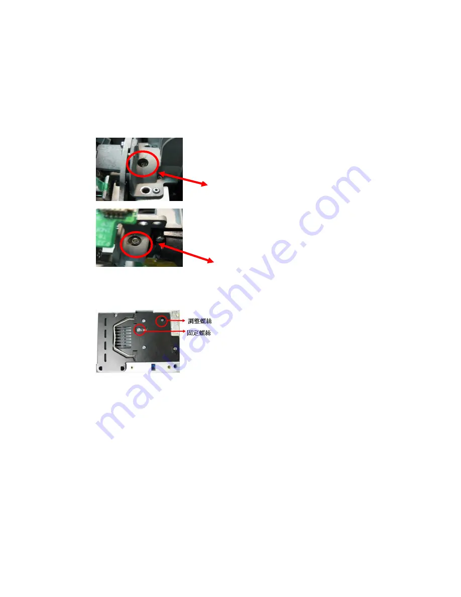
Step 1 : Adjust integration rod screw to eliminate color edge @ White pattern 


Step 2: Adjust lamp module angle to set the maximum brightness measured by CL200 


Screw

Screw

Screw

Screw 1

 1

 1

 1    

Screw 2 

1. Adjust the hexagonal screw in order to right and lift side 

color border disappeared.

 (

Enable just disappearing of 

right side color border on the full white pattern) 

2. Adjust the hexagonal screw in order to up and down side 

color border disappeared. By the color border is margin value on 

the down side of full white pattern. (Enable just disappearing of 

down side color border on the full white pattern) 


Loosed the fixed screw, CL200 is putted on the left corner of 

the screen

When full set is putted upside down

, to adjust the 

adjusted screw gets the highest luminance value then fixed 

the screw in the moment. 

=> Adjusted screw.       
=> Fixed screw. 

Summary of Contents for BS254

Page 1: ...Delta Elec Inc BS254 BX254 BX324 rev 06 Company Confidential LGE_______________________ Delta____________ 1 2011 06 16 DATA PROJECTOR BS254 BX254 BX324 SERVICE MANUAL ...

Page 2: ...ng the Remote Control Batteries 14 2 8 Block Diagram 15 3 TROUBLE SHOOTING 16 4 DISASSEMBLY AND ASSEMBLY 24 5 Flash Upgrade Flow 37 5 1 Projector RS 232 Drivers Installation Guide 37 5 2 DLP Projector Flash Tool firmware User Guide 42 5 3 Started with Download 43 5 4 Starting and Shutting down the Projector 49 5 5 Setting an Access Password Security Lock 51 5 6 Factroy Reset 53 5 7 Status 54 6 Cal...

Page 3: ...2903 change 3534117300 to 3534117301 01 20 2010 rev 02 Updated the spare part list page85 add the speaker in the list 05 17 2010 rev 03 Page86 Item8 and item9 change the photo position 07 07 2010 rev 04 Page84 Item9 change the part number from 3622403511 to 3622404311 LG P N no change 12 01 2010 rev 05 Page84 item17 change the LVPS Board P N from EBT61018601 to EBT61018602 04 07 2011 rev 06 Page85...

Page 4: ...d off sufficiently before carrying out repairs 3 Make sure that parts and screws and wiring etc are returned to their original positions Tube tape and other insulation materials have been used for safety reasons The internal wiring has been designed to avoid direct contact with hot parts or parts under high voltage when using clamps or other tools 4 The parts used in this device have special safet...

Page 5: ...ojection methods Front Rear Desktop Ceiling Rear Front Data compatibility IBM PC or compatibles VGA SVGA XGA SXGA UXGA Mac SDTV EDTV HDTV 480i 576i 480p 576p 720p 1080i 1080p Video compatibility NTSC PAL SECAM H Sync 15 30 91 4 KHz V Sync 43 87 Hz Safety certification FCC B UL cUL TUV CB CE PCT SASO NOM KC and CCC Operation temperature 5 35 C Dimensions 261 mm W x 78 mm H x 190 mm D WEIGHT 4 1 lbs...

Page 6: ...Delta Elec Inc BS254 BX254 BX324 rev 06 Company Confidential LGE_______________________ Delta____________ 6 2011 06 16 Audio IN 3 5 Mini jack Stereo Control Terminal RS 232 Security Kensington lock ...

Page 7: ...ight adjust button Push to release height adjuster 4 Height adjuster Adjusts level of projector 5 Lens Remove lens cap before use 6 Zoom ring Enlarges the projected image 7 Focus ring Focuses the projector image 8 Function keys See Top view on screen Display OSD buttons and LEDS 9 Height adjuster Adjusts level of projector Important Ventilation openings on the projector allow for good air circulat...

Page 8: ...enu Open and Exits the OSD buttons ON System over temperature 2 Temp LED OFF Normal state 3 Lamp LED Flashing Error code Green Power on Off Power off AC Off 4 Power LED Flashing Error off 5 Source Detects the input device 6 Up Cursor Keystone Navigates and changes settings in the OSD Quick Menu For Keystone 7 Down Cursor Keystone Navigates and changes settings in the OSD Quick Menu For Keystone ...

Page 9: ...____________________ Delta____________ 9 2011 04 07 8 Right Cursor OK Navigates and changes settings in the OSD Enter Menu 9 Power Turns the projector on or off 10 Left Cursor Auto Navigates and changes settings in the OSD Optimizes image size position and resolution ...

Page 10: ...nnect the POWER CABLE 3 VIDEO Connect the VIDEO CEBLE from a video device 4 S VIDEO Connect the S VIDEO CEBLE from a video device 5 AUDIO IN Connect the AUDIO CEBLE from the input device 6 RS 232 Connect the RS 232 CABLE from a computer 7 RGB Connect the RGB CABLE from a computer or components NOTE If you video equipment has both S VIDEO and RCA jacks composite video connect to the S VIDEO connect...

Page 11: ... cap hook Push to release adjustor 4 Tilt adjustor Rotate adjuster level to adjust angle position 5 Ceiling support holes Contact your dealer for information on mounting the projector on a ceiling NOTE When installing ensure that you see only UL Listed ceiling mounts The construction of the ceiling mount must be of a suitable shape and strength The ceiling mount load capacity must exceed the weigh...

Page 12: ...ghts can disrupt remote control operation 2 Be sure nothing obstructs the path between the remote control and the projector If the path between the remote control and the projector is obstructed you can bounce the signal off certain reflective surfaces such as projector screens 3 The buttons and keys on the projector have the same functions as the corresponding buttons on the remote control This u...

Page 13: ...ing size position 11 Keystone top Corrects image trapezoid wider bottom effect 12 Keystone bottom Corrects image trapezoid wider top effect 13 Down cursor Navigates and changes settings in the OSD 14 Left cursor Navigates and changes settings in the OSD 15 Menu Opens the OSD Remote Control Operating Range The remote control uses infrared transmission to control the projector It is not necessary to...

Page 14: ...ove the battery compartment cover by sliding the cover in the direction of the arrow A Pull out the cover B 2 Insert the battery with the positive side facing up 3 Replace the cover Caution 1 Only use a 3V lithium battery CR2025 2 Dispose of used batteries according to local ordinance regulations 3 Remove the battery when not using the projector for prolonged periods ...

Page 15: ...Delta Elec Inc BS254 BX254 BX324 rev 05 Company Confidential LG ______________________ Delta____________ 15 2011 04 07 2 8 Block Diagram ...

Page 16: ... the equipment Connect the power cord Power Supply Unit malfunction Check the connection of Power Supply LVPS BD CON3002 to MB P301 Check keypad connection MB P800 to Keypad P8100 Check voltage 12v 5v 3 3v 2 5v 1 8v 1 2v etc on Main Board Stand by Power Flashing Green Light Temp OFF Lamp OFF Yes Fan error Power Flashing Green Light6 Temp OFF Lamp Flashing Red Light 1 2 3 Check the system monitor f...

Page 17: ...ing Power On DMD error Power Flashing Green Light 8 Temp OFF Lamp OFF Yes DMD chip error Check DMD Board PWB Ass y No Lamp Cover A ssy is not attached Connector P802 on Main Board disconnected or Thermal break sensor is open Connector P803 on Main Board disconnected System error Power Flashing Green Light 4 or 7 Temp OFF Lamp OFF ...

Page 18: ...nnected Main Board or Ballast Ass y malfunction Ignition sound exists Lamp failure Lamp is broken damaged or burst System Change a new Lamp Lamp error Power OFF Temp OFF Lamp Static Red Normal operation Power Flashing Green Temp OFF Lamp OFF Flexible cable of Color Wheel Ass y is disconnected P708 or broken Index Board P8101 Main Board P704 is disconnected Index Board malfunction Color Wheel Ass y...

Page 19: ...ion No change occurs even after lamp replacement Press Menu key Remote controller set malfunction Low battery and outside operation rang Main Board Ass y malfunction Connector P704 P8103 of IR PWB disconnected IR PWB Ass y malfunction Check the pattern generator setting is wrong Main Board Ass y malfunction DMD Set malfunction Setting on PC side external output setting resolution etc Cable malfunc...

Page 20: ...connection Are abnormalities noticeable on projection screen Does the lamp go off during operation System OK Normal operation Temperature protector operated due to the increase in temperature based on operating environment Temperature protector operated due to blocked suction and exhaust holes or dirty fan No Yes Yes Fan error Power Flashing Green Light 6 Temp OFF Yes Connector P8002 of Fan discon...

Page 21: ...not in suspending mode Ensure a connected notebook computer is configured for an external display This is usually done by pressing an Fn key combination on the notebook Image Problems Problem No image appears on the screen 1 Verify the settings on your notebook or desktop PC 2 Turn off all equipment and power up again in the correct order Problem The image is blurred 1 Adjust the Focus on the proj...

Page 22: ...ture and Gamma settings on the Image menu of the OSD Lamp Problems Problem There is no light from the projector 9 Check that the power cable is securely connected 10 Ensure the power source is good by testing with another electrical device 11 Restart the projector in the correct order and check that the Power LED is green 12 If you have replaced the lamp recently try resetting the lamp connections...

Page 23: ... any fluorescent lights in the room 21 Check the battery polarity 22 Replace the batteries 23 Turn off other Infrared enabled devices in the vicinity 24 Have the remote control serviced Audio Problems Problem There is no sound 25 Adjust the volume on the remote control 26 Adjust the volume of the audio source 27 Check the audio cable connection 28 Test the source audio output with other speakers 2...

Page 24: ..._____ Delta____________ 24 2011 06 16 4 DIS ASSEMBLY AND ASSEMBLY Removing the Lamp Cover and Lamp Module Look the full set projector Look at the IO side Look at the keypad of top side Look at the keypad of top side D I S A S S E M B L Y Loose these two screws Review the lamp cover ...

Page 25: ..._____________ Delta____________ 25 2011 06 16 Removing the Lamp Cover and Lamp Module Loose these three screws and note this connector Take out the lamp module like this Remove the lamp modules upward view Look the Lamp 1 D I S A S S E M B L Y Look the Lamp 2 Look the Lamp 3 ...

Page 26: ... LG ______________________ Delta____________ 26 2011 06 16 Removing the Lamp Module and Front Cover Look at the bottom side Remove the four screws Look the screws S01 When assembly the front cover note these connector D I S A S S E M B L Y Review the front cover ...

Page 27: ..._______________ Delta____________ 27 2011 06 16 Removing the Top Cover and Main Board When assembly the top cover note these connectors Review the Top Cover Assy Review the projector Remove these screws D I S A S S E M B L Y Review the screws S01 S02 S03 Review the shield ...

Page 28: ...ial LG ______________________ Delta____________ 28 2011 06 16 Removing the Main Board Remove the five screws Review the five screws S02 Remove the four screws Review the four screws S04 D I S A S S E M B L Y Careful these connectors when you assembly the M B ...

Page 29: ...Delta Elec Inc BS254_BX254_BX324 rev 06 Company Confidential LG ______________________ Delta____________ 29 2011 06 16 Main Board Review D I S A S S E M B L Y Main Board Review Top side ...

Page 30: ...any Confidential LG ______________________ Delta____________ 30 2011 06 16 Main Board Review Main Board Review Bottom side D I S A S S E M B L Y P902 SPK P708 MOTOR P704 Index IR P8002 Fan2 P700 DMD P803 Therm P804 Ballast P8003 Fan3 P800 Keypad ...

Page 31: ..._________ Delta____________ 31 2011 06 16 Removing the Optical Engine Review the projector Remove the three screws and careful this shield when assembly Review the screws S01 Review the optical module 1 D I S A SS E M B L Y Review the optical module 2 Review the optical module 3 ...

Page 32: ..._ 32 2011 06 16 Removing the Optical Engine FAN and I O Panel Review the Projector Remove the two screws S01 and take out the Engine FAN Review the Optical Engine FAN Remove the three screws and careful when the wire when you assembly D I S A S S E M B L Y Review the three screws S05 Review the I O panel ...

Page 33: ...__________ Delta____________ 33 2011 06 16 Removing the Power LVPS Board Remove the three screws Review the three screws S01 Review the Power board Remove the two screws and careful the wire when assembly D I S A S S E M B L Y Review the two screws S05 S01 Review the LVPS Board ...

Page 34: ..._____________________ Delta____________ 34 2011 06 16 Removing the Lamp shield Lamp Fan Therm Switch Remove the three screws S01 Review the projector Remove the two screws S01 Review the two LAMP FANS D I S A S S E M B L Y Remove the two serews S01 Review these parts ...

Page 35: ...X254_BX324 rev 06 Company Confidential LG ______________________ Delta____________ 35 2011 06 16 Removing the ADJ ASSY Review Bottom case Remove the screws S01 Review the ADJ FOOT D I S A S S E M B L Y Review the Bottom Case ...

Page 36: ..._ 36 2011 06 16 ITEM DESCRIPTION P N S01 SCREW T φ3 1 06 8 PAN C S18C NI 3106160400 3 7 S02 SCREW M M2 0 4 5 FF C S P S20C NI 3105270500 2 3 S03 SCREW M M2 0 4 3 5 PAN C S20C NI 3105132600 2 3 S04 STAND OFF S18C HEX 4 7 4 F 4 40 M 4 40 3461431703 3 4 S05 SCREW M M3 0 5 6 FIL C EXT S20C ZN 3105469900 5 6 ...

Page 37: ... application software of a DLP projector The system requirement and the installation procedure of DLP Composer Lite v10 0 are also included in the document Note 1 User must have administrative privileges on the target computer in order to install the driver 2 The installation target directory must not be write protected User also required having the basic knowledge of Windows application installat...

Page 38: ...lta____________ 38 2011 06 16 Install DLP Composer Lite to PC Run the DLP Composer Lite v10 0 Setup exe The following pictures are illustrating the process of the Driver installation Start up page Click on the Next button to continue or Click on the Cancel button to cancel the installation ...

Page 39: ...lta____________ 39 2011 06 16 Click on the I accept agree to be bound by all the terms and conditions of this License Agreement point to continue Click on the Next button to continue Click on the Next button to continue The default installation direction is C Program Files DLP Composer 10 0 ...

Page 40: ...ault directory for saving the drive file somewhere else or Click on the Back button to return to the previous page or Click on the Cancel button to cancel the installation or Click on the Next button to continue Click on the Back button to return to the previous page or Click on the Next button to continue or Click on the Cancel button to cancel the installation ...

Page 41: ...__________ Delta____________ 41 2011 06 16 Please wait for the installation to complete Installation Completed Click on the Finish button with the Installation Completed Replicate the program file FlashDeviceParameters txt to PC under path C Program Files DLP Composer Lite 10 0 ...

Page 42: ...software of a DLP projector The system requirement and the installation procedure of DLP Composer Lite v10 0 are also included in the document Note 1 User must have administrative privileges on the target computer in order to install the driver 2 The installation target directory must not be write protected User also required having the basic knowledge of Windows application installation Attention...

Page 43: ... to illustrate the procedure to upgrade the application software of a DLP projector Step 1 Launch the DLP Composer Lite v10 0 from installed shortcut at Program DLP Composer TM Lite 10 0 DLP Composer TM Lite 10 0 exe Step 2 While executed The window shall appear as the following picture Click on the Edit button to continue to the DLP Composer Preferences page ...

Page 44: ...en press Down button and select Advance item Press Down button on the keypad to select Low Power Mode item Press the Enter button to set function to Off Step 4 Turn off the projector Step 5 Make sure that the RS 232 cable is firmly connected between projector and computer Step 6 Using the remote control and press Down Up Right Up keys in sequence using buttons The Power LED shall blink twice and t...

Page 45: ...______ Delta____________ 45 2011 06 16 Step 7 Click on the Communications button to continue to the Communications page Choose the Serial Port item of Projector Interface Select COM1 In use item Click on the Configure button to continue to the Serial Port Configuration page Step 8 ...

Page 46: ...TS Disable Click on the OK button to continue Step 8 Choose the Flash Loader item of DLP Composer Lite On the Flash Image File Press Browse button to locate the new firmware which can be downloaded from PC For example file name DP2404_LG_DVT03_20091119 img Select the desired img file by either double clicking the file or pressing the Open button ...

Page 47: ...v 06 Company Confidential LG ______________________ Delta____________ 47 2011 06 16 Step 9 Press the Start button to update the flash with the chosen firmware Step 10 A warning message box will appear for confirmation Press Y to continue ...

Page 48: ...4 rev 06 Company Confidential LG ______________________ Delta____________ 48 2011 06 16 Step 11 When the last warning message box appears this is the last chance to cancel the update Press Confirm button to start the firmware update ...

Page 49: ...ojector 1 Connect the power cord to the projector Connect the other end to a wall outlet The POWER LED on the projector lights 2 Turn on the connected devices 3 Then press the POWER button to turn on the projector The projector splash screen displays and connected devices are detected See Setting an Access Password Security Lock if security lock is enabled ...

Page 50: ...to COMPONENT ADAPTER RGB Analog RGB Component DVD input YCbCr YPbPr or HDTV input YPbPr via HD15 connector Composite Video Traditional composite video S Video Super video Y C separated 5 When the Power Off Press Power again message appears press the POWER button The projector turns off Caution 1 Be sure to remove the lens cap before starting projector 2 Do not unplug the power cord until the POWER...

Page 51: ...nd prevent unauthorized use of the projector When enabled the password must be entered after you power on the projector IMPORTANT Keep the password in a safe place Without the password you will not be able to use the projector If you lose the password contact your reseller for information on clearing the password 1 Press the MENU button to open the OSD menu 2 Press the cursor button to move to the...

Page 52: ...assword entry You can use any combination including the same arrow five times but not less than five Press the cursor buttons in any order to set the password Select Menu to exit the dialog box 7 The password confirm menu appears when user press the power on key in case the Security Lock is enabled Enter the password in the order you set it at step 5 8 Forget the password recovery only used in the...

Page 53: ...ial LG ______________________ Delta____________ 53 2011 06 16 5 6 Factory Reset Press the cursor button to move up and down in the Installation II menu Select the Factory Reset sub menu and press Enter to reset all the menu items to the factory default values ...

Page 54: ... down in the Installation II menu Select the Installation II sub menu and press Enter to enter the Status sub menu ITEM DESCRIPTION Active Source Display the activated source Video Information Displays resolution video information for RGB source and color standard for Video source Lamp Hours Lamp hour used information is displayed ECO and Normal counter are separated ...

Page 55: ... the projector press the MENU button on the keypad or IR controller Then select Installation II then press Down botton and select Advance Step 2 Press Right button on the keypad or Enter button by remote controller then select Lamp Hour Reset press Right button or Enter button Step 3 Press Enter button twice by remote control then press UP DOWN LEFT RIGHT by remote control ...

Page 56: ...B 1024 x 768 60Hz XGA 800 x 600 60Hz SVGA Step 1 In Service Mode select ADC Calibration VGA In this menu input pattern with White 240 240 240 and Black 16 16 16 for calibrate VGA Source After input ready press Enter or Right key to calibration Input Pattern Step 2 After complete the OSD will show the picture as follow if not complete just close the OSD Note Offset Gain Value Default After ADC Offs...

Page 57: ...elect ADC Calibration YUV In this menu input pattern with 75 SMPTE pattern for calibrate YUV Source and notice that the input source must be 480i format After input ready press Enter or Right key to proceed Input Pattern Step 2 After complete the OSD will show the picture as follow if not complete just close the OSD NOTE You can select Calibration Status VGA or Calibration Status YUV item to watch...

Page 58: ...768 60HZ XGA 800x600 60HZ SVGA B In service mode C Select CW INDEX Delay Time The default value is 340 The range is 0 719 D Switch Pattern 49 256 Gray Scale 1024 x 768 60Hz 800 x 600 60Hz Fine tune until the gray scale still distinct Decrease the color to the minimum tune off G B channel check the smooth in brighter level of the R 256 ramp If not fine tune CW INDEX Delay Time until R 256 ramp smoo...

Page 59: ...t and lift side color border disappeared Enable just disappearing of right side color border on the full white pattern 2 Adjust the hexagonal screw in order to up and down side color border disappeared By the color border is margin value on the down side of full white pattern Enable just disappearing of down side color border on the full white pattern Loosed the fixed screw CL200 is putted on the ...

Page 60: ...er from your local dealer 1 The projection lamp used in this product contains a small amount of mercury 2 Do not dispose this product with general household waste 3 Disposal of this product must be carried out in accordance with the regulations of your local authority Warning Be sure to turn off and unplug the projector at least 30 minutes before replacing the lamp Failure to do so could result in...

Page 61: ...ompany Confidential LG ______________________ Delta____________ 61 2011 06 16 3 Remove the three screws from the lamp module 4 Lift the module handle up 5 Disconnect the lamp connector Pull firmly on the module handle to remove the lamp module ...

Page 62: ..._______ 62 2011 06 16 6 Reverse steps 1 to 5 to install the new lamp module While installing align the lamp module with the connector and ensure it is level to avoid damage Note The lamp module must sit securely in place and the lamp connector must be connected properly before tightening the screws ...

Page 63: ...er to zero Refer to the following 1 Press the MENU button to open the OSD menu 2 Press the cursor button to move to the Installation II menu Press the cursor button to move down to Advanced 3 Press the cursor button to move down to Lamp Hour Reset 4 Press the cursor or enter button A message screen appears 5 6 Press buttons to reset the lamp hour Press the menu button to get back to the Installati...

Page 64: ... projector interior when cleaning have the projector serviced 9 2 Cleaning the Lens You can purchase optic lens cleaner from most camera stores Refer to the following to clean the projector lens 1 Apply a little optic lens cleaner to a clean soft cloth Do not apply the cleaner directly to the lens 2 Lightly wipe the lens in a circular motion Caution 1 Do not use abrasive cleaners or solvents 2 To ...

Page 65: ...se peeling of the color filter 3 Cleaning the DMD The DMD surface is glass and can be cleaned However avoid scratches as these can have a direct influence on the image In case of dust on the DMD surface use an air cleaner with a device to prevent static if possible to clean off the surface In case of fingerprints etc add a small amount of water to the designated glass cleaner and wipe off in one d...

Page 66: ...ove the battery compartment cover by sliding the cover in the direction of the arrow A Pull out the cover B 2 Insert the battery with the positive side facing up 3 Replace the cover Caution 1 Only use a 3V lithium battery CR2025 2 Dispose of used batteries according to local ordinance regulations 3 Remove the battery when not using the projector for prolonged periods ...

Page 67: ...INK ORANGE Over temperature OFF ON OFF Thermal break status error 4 OFF OFF Lamp error 5 OFF OFF Fan1 error 6 OFF 1 Fan2 error 6 OFF 2 Fan3 error 6 OFF 3 Lamp door open 7 OFF OFF DMD error 8 OFF OFF Color wheel error 9 OFF OFF In the event of an error please disconnect the AC power cord and wait for one 1 minute before restarting the projector If the POWER or LAMP LED are still blinking or the ove...

Page 68: ...e projector Signal Resolution H Sync KHz V Sync Hz Composite S Video Component RGB NTSC 15 734 60 0 PAL SECAM 15 625 50 0 720 x 400 37 9 85 0 640 x 480 31 5 60 0 640 x 480 37 9 72 8 640 x 480 37 5 75 0 640 x 480 43 3 85 0 800 x 600 35 2 56 3 800 x 600 37 9 60 3 800 x 600 48 1 72 2 800 x 600 46 9 75 0 800 x 600 53 7 85 1 1024 x 768 48 4 60 0 1024 x 768 56 5 70 1 1024 x 768 60 0 75 0 1024 x 768 68 7...

Page 69: ...0 66 7 832 x 624 49 7 74 5 1024 x 768 60 2 74 9 Apple Macintosh 1152 x 870 68 7 75 1 480i 15 734 60 SDTV 576i 15 625 50 480p 31 5 60 EDTV 576p 31 3 50 720p 37 5 50 720p 45 0 60 1080i 33 8 60 1080i 28 1 50 1080p 67 5 60 HDTV 1080p 56 3 50 Supported frequency Frequency not supported Displayable level The resolution of the panel for the BS254 is 800 x 600 and1024 x 768 is for the BX254 BX354 Resoluti...

Page 70: ...rojection Distance ITEM TELE WIDE Distance m 1 32 3 58 4 39 8 78 1 57 3 14 3 93 11 77 Diagonal inches 30 80 100 200 40 80 100 300 Keystone degree 12 5 12 5 12 5 12 5 13 9 13 9 13 9 13 9 Image Height mm 457 1219 1524 1864 610 1219 1524 4527 Image Width mm 610 1626 2032 3762 813 1626 2032 6096 A mm 64 171 213 427 85 171 213 640 ...

Page 71: ..._ 0101 Hex 257 Dec 12 15 Last 5 Digits of Serial Number ______ 16843009 Dec 01010101 Hex 16 Week of Manufacture _________________ 1 17 Year of Manufacture _________________ 2009 18 EDID Version Number _________________ 1 19 EDID Revision Number ________________ 3 20 VIDEO INPUT DEFINITION Analog Signal 0 700V 0 300V Separate Composite Sync on Green 21 Maximum Horizontal Image Size _______ 0 mm 22 ...

Page 72: ... BlueX 0 135 BlueY 0 073 WhiteX 0 303 WhiteY 0 341 35 ESTABLISHED TIMING I 720 X 400 70Hz IBM VGA 640 X 480 60Hz IBM VGA 640 X 480 67Hz Apple Mac II 640 X 480 72Hz VESA 640 X 480 75Hz VESA 800 X 600 56Hz VESA 800 X 600 60Hz VESA 36 ESTABLISHED TIMING II 800 X 600 72Hz VESA 800 X 600 75Hz VESA 832 X 624 75Hz Apple Mac II 1024 X 768 60Hz VESA 1024 X 768 70Hz VESA 1024 X 768 75Hz VESA 1280 X 1024 75H...

Page 73: ...on Interlaced Horizontal Active Time 800 pixels Blanking Time 256 pixels Sync Offset 40 pixels Sync Pulse Width 128 pixels Border 0 pixels Vertical Active Time 600 lines Blanking Time 28 lines Sync Offse 1 lines Sync Pulse Width 4 lines Border 0 lines None Normal Digital Separate Horizontal Polarity Vertical Polarity 72 89 Detailed Timing Descriptor Block 2 Monitor Serial Number 90 107 Detailed Ti...

Page 74: ...324 rev 06 Company Confidential LG ______________________ Delta____________ 74 2011 06 16 B BX254 SD DP 3407 EDID Version 1 Revision 3 DDC Test For GSM BX254 SD C BX324 SD DP 3408 EDID Version 1 Revision 3 DDC Test For GSM BX324 SD ...

Page 75: ...54_BX324 rev 06 Company Confidential LG ______________________ Delta____________ 75 2011 06 16 12 RS232 RS232 Setting Baud rate 9600 Parity check None Data bit 8 Stop bit 1 Flow Control None Minimum delay for next command 1ms ...

Page 76: ...___________ 76 2011 06 16 Hyper Terminal setting guide 1 Connect the RS232 Cable between your computer and Projector 2 Open HyperTerminal Window2000 XP HyperTerminal path Start Programs Accessories Communications HyperTerminal Setting the HyperTerminal parameter Step 1 Type the connection name ...

Page 77: ...254_BX324 rev 06 Company Confidential LG ______________________ Delta____________ 77 2011 06 16 Step2 Choose the COM port for your RS232 Cable connected to Step3 In Bits per second choose 9600 and in Flow control choose None ...

Page 78: ..._BX324 rev 06 Company Confidential LG ______________________ Delta____________ 78 2011 06 16 Step4 Click the File and choose Properties to setting Keyboard parameter Step5 In Setting page choose Emulation type for your keyboard ...

Page 79: ... Confidential LG ______________________ Delta____________ 79 2011 06 16 Step6 Click ASCII Setting icon to setup ASCII code parameter Step7 Mark Send Line ends with line feeds and Echo typed characters locally and click OK bottom to complete setting ...

Page 80: ...R Control Sequence The projector may send a return code after it received a command If the command isn t received correctly the projector will not send the return code Operation Command The operation commands execute the basic operation setting of this projector Operation ASCII HEX Power On P N CR 7Eh 50h 4Eh 0Dh Power Off P F CR 7Eh 50h 46h 0Dh Auto Image A I CR 7Eh 41h 49h 0Dh Lamp Hour Reset R ...

Page 81: ... KEYSTONE r K CR 7Eh 72h 4Bh 0Dh KEYSTONE r J CR 7Eh 72h 4Ah 0Dh MENU r M CR 7Eh 72h 4Dh 0Dh STATUS r S CR 7Eh 72h 53h 0Dh MUTE r T CR 7Eh 72h 54h 0Dh ZOOM r Z CR 7Eh 72h 5Ah 0Dh ZOOM r Y CR 7Eh 72h 59h 0Dh BLANK r B CR 7Eh 72h 42h 0Dh FREEZE r F CR 7Eh 72h 46h 0Dh VOLUME r V CR 7Eh 72h 56h 0Dh VOLUME r W CR 7Eh 72h 57h 0Dh Enter r N CR 7Eh 72h 4Eh 0Dh Set Value Command ITEM ASCII HEX Brightness s...

Page 82: ... Ceiling ALL Attention Data range may be different for different models Example 1 Adjust Brightness value to 100 Send Command sB100CR Example 2 Adjust Color Temperature to Warm Send Command sT2CR Query Command ITEM ASCII HEX Software Version q V CR 7Eh 71h 56h 0Dh Power State q P CR 7Eh 71h 50h 0Dh Input Select q S CR 7Eh 71h 53h 0Dh Lamp Hours q L CR 7Eh 71h 4Ch 0Dh Brightness q B CR 7Eh 71h 42h ...

Page 83: ...n Power State On Off Input Select RGB Video S Video Component Lamp Hours 2000 Brightness 100 Contrast 100 Color Video 100 Tint Video 100 Scaling Fill 4 3 16 9 LetterBox Native Color Temperature Cold Normal Warm Projection Mode Front Rear Ceiling Rear Ceiling Example 1 Get Brightness value Send Command qBCR Response 100 Example 2 Get Color Temperature Send Command qTCR Response Warm ...

Page 84: ...SSY AUB0612VHD SM00 L70 25 60 S V V V 11 EBT61018001 5600601264 PWB ASSY MAIN BD J5P ULTRA 02 V 12 EBT61018101 5600601393 PWB ASSY MAIN BD J5P ULTRA 02 02 V 13 EBT61018201 5600601395 PWB ASSY MAIN BD J5P ULTRA 02 03 V 14 EBT61018301 5600601366 PWB ASSY POWER BALLAST V V 15 EBT61018401 5600601363 PWB ASSY POWER BALLAST V 16 EBT61018501 5600601241 PWB ASSY DMD BD J5P ULTRA 01 V V V 17 EBT61018601 EB...

Page 85: ... MKJ42367902 5041819000 REMOTE CONTROLLER 15KEYS V V V 33 MFA42499604 3392122800 ADJ FOOT FRONT PC ABS 94V0 GRAY V V V 34 MFA42499702 3245068400 FOOT SIRUB V 0 41 8 12 2 4 8 BLK V V V 35 MFA55194901 3392057400 FOOT RING PC 94V0 BLK V V V 36 MCK63607901 3245033800 FOOT RUBBER 94V0 14 4 6 1 BLK V V V 37 MEG42520801 3461431703 Hexagonal Screw STAND OFF S18C HEX 4 7 4 F 4 40 M 4 V V V 38 MEG42522002 3...

Page 86: ...Company Confidential LG ______________________ Delta____________ 2 3 4 5 6 7 8 9 10 12 14 16 17 18 19 20 22 24 26 27 28 29 30 31 32 33 34 35 36 37 38 40 A ...

Reviews: