background image

ENGLISH

Installation Manual 

15

Installation 

Cleaning and Flushing the Water Loop

Water Connection

For vibration isolation, it is recommended that flexible steel braided hoses be in stalled instead of
hard piping between the vertical risers and the unit chassis.

Supply Grille installation

1. Install the supply grille(s) into the cabinet discharge opening. Insure there are no air gaps

between the cabinet supply air and the grille. This helps prevent recirculation of supply air into the
return air opening behind the drywall.

2. Secure grille(s) into the drywall via two screws.

Cleaning and flushing the Water Loop

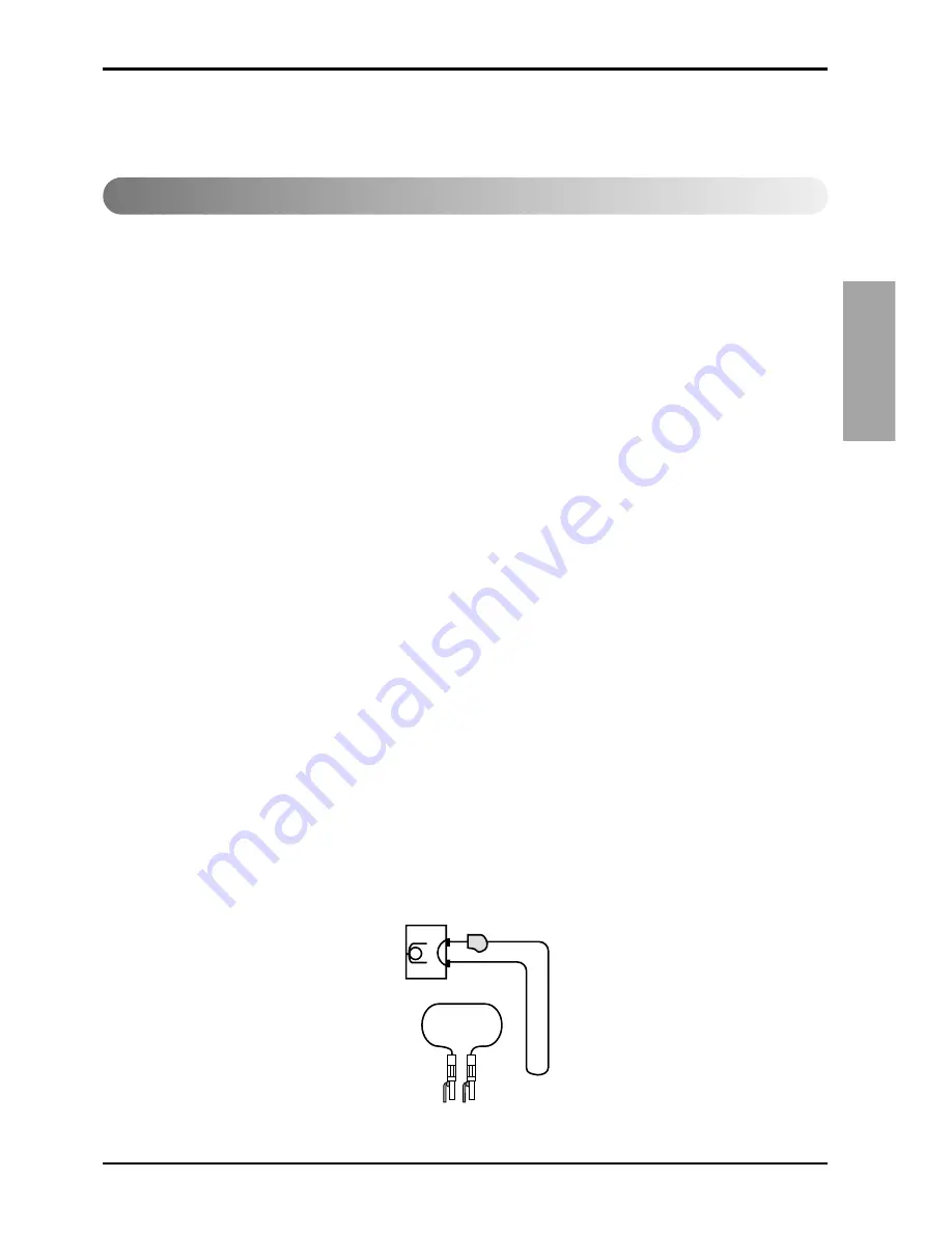
After the piping system is complete, the flexible hose connector should be doubled back to
complete the water circuit external to the unit (avoiding trash settle-ut in the condenser). An extra
pipe may be necessary to connect the hose kits. See page 15 for antifreeze/water mixture by
volume.

3. Water circulation system should be filled with clean water using the water make up connections.

Note:

Air vents should be opened during filling.

4. With the air vents closed, start the circulating pump and then crack the air vents to bled off the

trapped air, assuring circulation through all components of the system.

Note:

Make up water must be available to the system to replace the volume formerly occupied by
the air that is bled off.

5. With the air vented and the water circulating, the entire  system should be checked for leaks with

repairs made as required.

6. Operate the supplementary heat system making checks per manufacturer's instructions. During

this operation, visual checks should be made for leaks that may have occurred due to increased
heat. Repair as required.

7. Open the system at the lowest point for the initial  blow down (making sure the make up water is

equal to the water being dumped). Continue blow down until the water leaving the drain runs
clear, but not less than 2 hours.

8. Shut down pumps and supplementary heat system. Reconnect the hoses placing the water-to

refrigerant heat exchanger  in the water circulating system.

Note:

Vents should be open when the pumps and supplementary heat system are shut down.

Flushing the water loop

Summary of Contents for AKWW0093AA0

Page 1: ...ce com techsup html IMPORTANT Please read this instruction sheet completely before installing the product When the power cord is damaged replacement work shall be performed by authorized personnel only Installation work must be performed in accordance with the national wiring standards by authorized personnel only Please retain this owner s manual for future reference after reading it thoroughly E...

Page 2: ... Installation 10 Installation Parts 10 Installation Tools 10 Weights Clearance 11 Installation 13 Pre Start up Checklist 17 Maintenance 18 Panel Return Grille Discharge Hose Flexible 1 2 Remote controller Screw driver Electric drill Specified torque wrenches Spanner Ohmmeter Ammeter Thermometer Horizontal meter Pipe wrench Installation Requirements Required Parts Required Tools ...

Page 3: ...g can cause accidental injury or death Ground the unit following local electrical codes Connect all wiring tightly Loose wiring may cause overheating at connection points and a possible fire hazard This air conditioning system meets strict safety and operating standards As the installer or service person it is an important part of your job to install or service the system so it operates safely and...

Page 4: ...ications Meanings of symbols used in this manual are as shown below This symbol indicates the possibility of death or serious injury This symbol indicates the possibility of injury or damage to properties only Installation Gasolin Do not place the power cord near a heater It may cause fire and electric shock See features section Do not use the power cord near flammable gas or combustibles such as ...

Page 5: ...ecified power cord It will cause electric shock or fire Do not modify power cord length It will cause electric shock or fire due to heat generation Always plug into a grounded outlet No grounding may cause electric shock See Installation Manual Unplug the unit if strange sounds odors or smoke come from it Otherwise it may cause fire and electric shock accident ON Do not operate with wet hands or i...

Page 6: ...ut It may cause explosion fire and burn Never touch the metal parts of the unit when removing the filter They are sharp and may cause injury Do not block the inlet or outlet It may cause failure of appliance or accident Be cautious not to touch the sharp edges when installing It may cause injury Turn off the main power switch when not using it for a long time Prevent accidental startup and the pos...

Page 7: ...speed during operation it may cause injury Do not put a pet or house plant where it will be exposed to direct air flow This could injure the pet or plant Do not use this appliance for special purposes such as pets foods precision machinery or objects of art It is an air conditioner not a precision refrigeration system Always insert the filter securely Clean it every two weeks Operation without fil...

Page 8: ...ctric shock This symbol alerts you to hazards that could cause harm to the air conditioner This symbol indicates special notes NOTICE Introduction Symbols Used in this Manual Features AKWW0243AA0 AKWW0243YA0 AKWW0183AA0 AKWW0183YA0 AKWW0123AA0 AKWW0123YA0 AKWW0093AA0 AKWW0093YA0 ...

Page 9: ...ENGLISH Installation Manual 9 CAUTION Be cautious not to touch the sharp edges when installing It may cause injury Introduction L1 L2 ...

Page 10: ... Introduction 1 6 1 6 16 7 1 6 5 1 3 7 12 6 3 7 35 4 3 2 49 4 5 9 20 20 84 7 10 2 16 7 Unit inch 18 3 49 18 7 17 5 18 8 Unit inch AKWW0243AA0 AKWW0183AA0 AKWW0123AA0 AKWW0093AA0 AKWW0243YA0 AKWW0183YA0 AKWW0123YA0 AKWW0093YA0 ...

Page 11: ...e Ohmmeter Ammeter Thermometer Horizontal meter Name 1 2 24 1 2 24 21 9 52 6 2 49 4 8 7 3 1 28 5 3 1 9 1 1 6 18 7 1 6 Unit inch Unit inch 18 11 8 1 8 1 7 3 9 3 9 4 7 8 5 Recommended to use part supplied by LG Recommended to use part supplied by LG Recommended to use part supplied by LG Not supplied by LG Installation Parts Option Installation Tools Installation Read completely then follow step by ...

Page 12: ...vice clearance and technician safety The unit chassis should be easily removed from the cabinet in all applications There must be enough space for service personnel to perform maintenance or repair Provide sufficient room to make water and electrical connection s Local and national codes should be followed in providing electrical power connections See below figure for mechanical clearances Model N...

Page 13: ...R DOOR FRAME 1 X 1 CLOSED CELL INSULATION 1 X 1 CLOSED CELL INSULATION 3 1 2 3 8 1 1 4 1 2 0 1 1 4 1 2 0 A 1 X 1 CLOSED CELL INSULATION 1 X 1 CLOSED CELL INSULATION 2 X 4 STUD 2 X 4 STUD RETURN AIR OPENING FLANGE ON CABINET RETURN AIR OPENING FLANGE ON CABINET SHEETROCK SHEETROCK RETURN AIR DOOR FLANGE CABINET CABINET Finished wall and framing should not touch the unit cabinetry NOTE A B 21 3 542 ...

Page 14: ...ent risers during positioning The riser should fall approximately 2 into the 3 swage This will allow for the variation in floor to floor dimensions and keep the riser joints from bottoming out 3 Level the cabinet 4 Plum bribers in two planes to as sure proper unit operation and condensate drainage 5 Anchor all units into place 6 For field provided risers center the supply return stubou is into the...

Page 15: ...ter make up connections Note Air vents should be opened during filling 4 With the air vents closed start the circulating pump and then crack the air vents to bled off the trapped air assuring circulation through all components of the system Note Make up water must be available to the system to replace the volume formerly occupied by the air that is bled off 5 With the air vented and the water circ...

Page 16: ... AKWW0123YA0 20A 100mmA 0 1sec 20A 0 005 0 005 AKWW0183YA0 AWG 25A 100mmA 0 1sec Leak current circuit breaker ELB 25A Circuit breaker NFB 0 005 0 005 Min Thickness Main Earth AKWW0243YA0 inch2 Model RECOMMAND Provide a circuit breaker between power source and the unit as shown below RECOMMAND The power cord connected to the unit should be complied with the following specifications ETL recognized a...

Page 17: ...switch 1 Connect the power cable to the right side of manual controllers switch via clamp cord 2 Put the earth with grounding screw 3 Connect the lead wire from manual controllers switch to terminal block in control box refer to the wiring diagram Manual controllers switch Power cable Earth cable L1 L2 L1 L2 L1 L2 ...

Page 18: ...e wire end with a wire cutter or wire cutting pliers then strip the insulation to expose the strand wiring about 10mm 3 8 2 Using a screwdriver remove the terminal screw s on the terminal manual controllers switch plate 3 Using a round terminal fastener or pliers securely clamp each stripped wire end with a round terminal 4 Position the round terminal wire and replace and tighten the terminal scre...

Page 19: ...age main drain pipe Vinyl tape Adhesive Drain hose Unit drain hose narrow Do not raise To check the drainage 1 Pour a glass of water on the evaporator 2 Ensure the water flows through the drain hose of the unit without any leakage and goes out the drain exit When extending the drain hose at the unit install the drain pipe Drain piping 1 The drain hose should point downward for easy drain flow 2 Do...

Page 20: ...w to connect the water hose Remove the cover of front panel Connect supply and return water hoses refer to the label index Water Out Water Out Water Out Water In Water In Wrench Pipe Water in out Hose flexible Nut hose Open end wrench fixed ...

Page 21: ...ect the remote controller lead wire 1 Remove the cover of front panel 2 Remove the cover of control box 3 Connect remote controller lead wire to the indoor PCB via hole on the control box refer to the Wiring diagram Conduit Remote controller leadwire L1 L2 ...

Page 22: ...e Do not embed the remote controller into the wall It may cause the breakdown of the temperature sensor If you want to install a number of remote controller at the same place in a vertical line install them at regular intervals of 2cm It may cause the breakdown of the temperature sensor Do not install the cable with a distance of 50 m or longer This can cause communication error When installing th...

Page 23: ...ll the chassis to the cabinet 1 Assemble the cover of control box 2 Assemble the chassis to the cabinet by sliding 3 Assemble the cover of front panel 4 Assemble the filter to the front of evaporator 5 Assemble the return panel to the cabinet mating to hinge ...

Page 24: ...g Follow proper lockout tagout procedures to ensure the power can not be inadvertently energized Failure to disconnect power before servicing could result in death or serious injury The transformer is located in the chassis control box Main Electrical 1 Verify the power supply complies with the unit nameplate specifications 2 Inspect all control panel components tighten any loose connections 3 Con...

Page 25: ...t components The location of the drywall may be dependent upon the type of return air access design Units that contain a field provided return air access assembly contractor must calculate location of drywall to allow for frame mounting Units utilizing Hinged Acoustic Door Assembly 1 Locate the side studs a minimum of 1 1 4 inches and a maximum of 1 3 8 inches from the cabinet to the side of the s...

Page 26: ... grille This helps prevent recirculation of supply air into the return air opening behind the drywall 2 Secure grille s into the drywall via two screws Cleaning and Flushing the Water Loop 1 After the piping system is complete the flexible hose connectors should be doubled back to complete the water circuit external to the unit avoiding trash settle out in the condenser An extra pipe may be necess...

Page 27: ...ature for Freeze Protection 10 F 15 F 20 F 25 F 30 F Methanol 25 21 16 10 3 Propylene Glycol 6 Before energizing the unit the following system devices must be checked Is the high voltage power supply correct and in accordance with the nameplate ratings Is the field wiring and circuit protection the correct size Is the low voltage control circuit wiring correct per the unit wiring diagram Is the pi...

Page 28: ...ck flushed and cleaned with a chemical that will remove the scale This service should be performed by an experienced service person Hazardous Chemicals Coil cleaning agents can be either acidic or highly alkaline Handle chemical carefully Proper handling should include goggles or face shield chemical resistant gloves boots apron or suit as required For personal safety refer to the cleaning agent m...

Page 29: ...P No MFL30215306 ...

Reviews: