


10
LG
Air-Cooled Cooling Only Inverter Scroll Chiller Installation and Owners Manual
Due to our policy of continuous product innovation, some specifications may change without notification.
©LG Electronics U.S.A., Inc., Englewood Cliffs, NJ. All rights reserved. “LG” is a registered trademark of LG Corp.
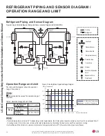
Partial Load Operation
Each cooling cycle operates independently; one (1) cooling cycle
includes two (2) inverter compressors as shown in the diagram.
Two (2) inverter compressors increase the rpm after initial start to
gradually increase the cooling capacity. The user can operate the
chiller smoothly, at optimal conditions, by setting the cooling capac-
ity based on the linear control of LG chiller controller. LG chillers
have efficient partial load performance at any load.
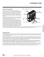
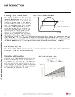
Cooling Cycle Description
The cooling cycle of ACAH series can be described using
the following pressure–enthalpy chart.
༃
,
༄
,
༅
,
༆
,
and
༇
in the following chart shows the conditions of the
refrigerant. The refrigerant comes into the compressor
motor and cools the motor, and becomes overheated and
moves to the suction inlet of the compressor. The oil inside
the compressor seals the gap between the compressor
scrolls and provides lubrication for the bearing to help the
compression of the refrigerant. During this time, the refrig-
erant is compressed and is discharged to the air cooled
condenser. (
༄Ϳ
The compressed refrigerant passes
through the air cooled condenser and exchanges the heat
with the outdoor air. The condensed refrigerant then passes
the condenser to be overcooled. (
༄
ĺ
༅
ĺ
༆
). The refrigerant that passed through the condenser expands in the electronic expansion valve
to flow to the evaporator. (
༆
ĺ
༇
). The refrigerant is evaporated in the shell and tube type heat exchanger, the evaporator. (
༇
ĺ
༃
). Liquid
refrigerant of low temperature pressure passes through the evaporator to cool the water flowing into the evaporator and the refrigerant itself receives
the heat to evaporate to gas condition. (
༃
) The refrigerant continues to change the phase and continuously repeats the cooling cycle.
1
r
o
s
s
e
r
p
m
o
c
d
e
e
p
s
c
it
a
t
Sy
ti
c
a
p
a
c
g
n
il
o
o
C
Load (%)
25%
50%
75%
100%
50%
25%
75%
100%
0%
Inverter
Compressor 1
Inverter
Compressor 2
Cooling Capacity
Capacity (%)
Lubrication System
Oil is efficiently separated inside the scroll compressor, and even when the cycle operates, most of the oil remains inside. Only a part of the
oil will mix with the refrigerant to be circulated within the cycle.
Figure 3: Partial Load Operation Diagram.
Pressure
Enthalpy
Hot-Gas
Suction
-
Compressor
Figure 2: LG Chiller Pressure-Enthalpy Diagram.
INTRODUCTION