background image

TUYAUX DE RACCORDEMENT

14

ENGLISH

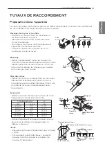
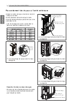
Raccordement des tuyaux à l'unité extérieure

Alignez le centre du tuyau et serrez le raccord 
 conique à la main.

Serrez ensuite le raccord conique à l'aide 
d'une clé dynamométrique jusqu'à ce que vous 
entendiez un clic.

- Lors du serrage avec la clé, suivez bien la 
  flèche de direction indiquée sur la clé.

Clé dy-
namométrique

Conti-
 nu

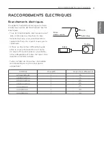
Tuyauterie côté gaz

Tuyauterie côté liquide

Tuyau de vidange

Fil de connexion

Diamètre extérieur

Couple

mm

pouce

N m

Ø 6.35

1/4

16±2

Ø 9.52

3/8

38±4

Ø 12.7

1/2

55±6

Ø 15.88

5/8

75±7

Ø 19.05

3/4

110±10

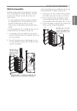
- Bouchez les trous traversants avec du mastic 
  ou un matériau isolant (acheté localement) 
  pour remplir les écarts.

Clé dynamométrique

Tuyauterie côté liquide
(diamètre plus petit)

Tuyauterie côté gaz
(diamètre plus grand)

Lors de serrage du tuyau, tenez le corps 
hexagonal.

Empêcher l'entrée de corps étrangers

Lors de serrage du tuyau, tenez le corps 
hexagonal.

Lors de serrage du tuyau, tenez le corps 
hexagonal.

Lors de serrage du tuyau, tenez le corps 
hexagonal.

Clé dynamométrique

Tuyauterie côté liquide
  (diamètre plus petit)

Tuyauterie côté gaz
  (diamètre plus grand)

Clé dy-
namométrique

Conti-
 nu

Summary of Contents for ABUQ22GM1A4

Page 1: ...Installation work must be performed in accordance with the national wiring standards by authorized personnel only Please retain this installation manual for future reference after reading it thoroughly Copyright 2016 2019 LG Electronics Inc All Rights Reserved www lg com ENGLISH ...

Page 2: ...ay deteriorate if the air condition er is used for many hours Clean the air filter once every 2 weeks Dust and impurities collected in the air filter may block the air flow or weaken the cooling dehumidifying functions For your records Staple your receipt to this page in case you need it to prove the date of purchase or for warranty purposes Write the model number and the serial number here Model ...

Page 3: ... JU NBZ DBVTF B żSF FMFDUSJDBM TIPDL FYQMPTion or injury ţ 4FDVSFMZ BUUBDI UIF FMFDUSJDBM QBSU DPWFS UP UIF JOEPPS VOJU and the service panel to the outdoor unit If the electrical part cover of the indoor unit and the service panel of the outdoor unit are OPU BUUBDIFE TFDVSFMZ JU DPVME SFTVMU JO B żSF PS FMFDUSJD TIPck due to dust water etc ţ MXBZT JOTUBMM BO FBSUI MFBLBHF DJSDVJU CSFBLFS BOE B EF...

Page 4: ...al shock Do not open the suction inlet of the indoor outdoor unit during operation Otherwise it may electrical shock and failure Do not allow water to run into electrical parts Otherwise it may cause the failure of machine or electrical shock Do not touch the power cable with wet hands It may cause electric shock and damage Never touch the metal parts of the unit when removing the filter They are ...

Page 5: ...IFSXJTF JU NBZ DBVTF WJCSBUJPO PS XBUFS MFBL ţ FBOT GPS EJTDPOOFDUJPO NVTU CF JODPSQPSBUFE JO UIF żYFE XJSJOH JO BDDPSEBODF XJUI UIF XJSJOH SVMFT BHF 0QFSBUJPO ţ WPJE FYDFTTJWF DPPMJOH BOE QFSGPSN WFOUJMBUJPO TPNFUJNFT 0UIFSXJTF JU NBZ EP IBSN UP ZPVS IFBMUI ţ 6TF B TPGU DMPUI UP DMFBO P OPU VTF XBY UIJOOFS PS B TUSPOH EFUFSHFOU 5IF BQQFBSBODF PG UIF BJS DPOEJUJPOFS NBZ EFUFSJPSBUF DIBOHF DPMPS PS...

Page 6: ...n Indoor Unit and Outdoor Unit 12 Connecting the cable to Outdoor Unit 13 CONNECTING PIPES 13 Preparation of Piping 14 Connecting the pipes to the Outdoor unit 15 Forming the Piping 16 LEAKAGE TEST AND EVACUATION 16 Preparation 16 Leakage test 17 Evacuation 18 TEST RUNNING 20INSTALLATION GUIDE AT THE SEASIDE 21 CONVENIENT FUNC TIONS 21 Pressure compensation function TABLE OF CONTENTS ...

Page 7: ...ighbors More than 300 mm Fence or obstacles More than 700 mm More than 600 mm More than 300mm More than 300 mm Sunroof Unit mm Installation Places INSTALLATION OF OUTDOOR UNIT Piping length and the elevation Ceiling Suspended Air conditioner MODEL Pipe Size Length A m Elevation B m Additional Refrigerant g m Gas Liquid Standard Max Standard Max Ø 15 88 5 8 Ø 9 52 3 8 Ø 15 88 5 8 Ø 9 52 3 8 Ø 12 7 ...

Page 8: ...ţ BQBDJUZ JT CBTFE PO TUBOEBSE MFOHUI BOE NBYJNVN BMMPXBODF MFOHUI JT PO UIF CBTJT PG SFMJBCJMJUZ ţ NQSPQFS SFGSJHFSBOU DIBSHF NBZ SFTVMU JO BCOPSNBM DZDMF CAUTION G JOTUBMMFE UVCF JT TIPSUFS UIBO N BEEJUJPOBM DIBSHJOH JT OPU OFDFTTBSZ EEJUJPOBM 3FGSJHFSBOU Y EEJUJPOBM SFGSJHFSBOU H ENGLISH ...

Page 9: ...e a recognized ELCB Electric Leakage Circuit Breaker between the power source and the unit A disconnection device to ade quately disconnect all supply lines must be fitted Model of circuit breaker recommended by authorized personnel only Outdoor Indoor Main power source Switch box ELCB WIRING CONNECTION Model Phase Ø ELCB 1 25 1 15 1 15 1 30 1 40 WIRING CONNECTION 9 ATUQ30GPLA4 1 25 ABUQ30GM1A4 1 2...

Page 10: ...h a cord set complying with the national regulation If the supply cord is damaged it must be replaced by a special cord or assembly availible from the manufacturer of its service agent When the connection line between the indoor unit and out dooor unit is over 40 m connect the telecommunication line and power line separately CAUTION GN YL 20 mm 35 5 mm 10 3 mm NORMAL CROSS SECTIONAL AREA 0 75 mm2 ...

Page 11: ... designated power wire and connect firmly then secure to prevent outside pressure being exerted on the terminal block Use an appropriate screwdriver for tightening the terinal screws A screwdriver with a small head will strip the head and make proper tighterning impossible Over tightening the terminal screws may break them Round pressure terminal Power wire Connect same thickness wiring to both si...

Page 12: ...l provided in the control box and do earthing Make sure the rubber bushes are properly used in knock out holes after connecting main power Tubing Cover Power cord Power connecting cable CAUTION 12 WIRING CONNECTION ENGLISH Power connecring cable Power cord Tubing Cover Make sure the rubber bushes are properly used in knock out holes after connecting main power 1 L 2 N 1 L 2 N 3 1 L 2 N 1 L 2 N 3 ...

Page 13: ...ts attached to indoor and outdoor unit then put them on pipe tube having completed burr removal not possible to put them on after flaring work Flaring work Carry out flaring work using flaring tool as shown below Firmly hold copper pipe in a bar in the dimension shown in the table below Check Compare the flared work with figure below If flare is noted to be defective cut off the flared section and...

Page 14: ...ping Drain hose Connecting wire When tighten the pipe hold the haxago nal body When tighten the pipe hold the haxago nal body When tighten the pipe hold the haxago nal body Outside diameter Torque mm inch N m Ø 6 35 1 4 16 2 Ø 9 52 3 8 38 4 Ø 12 7 1 2 55 6 Ø 15 88 5 8 75 7 Ø 19 05 3 4 110 10 Preventing foreign objects from entering Plug the pipe through holes with putty or insulation material proc...

Page 15: ...d above the Indoor unit perform the following 1 Tape the piping and connecting cable from down to up 2 Secure the taped piping along the exterior wall Form a trap to prevent water entering the room 3 Fix the piping onto the wall by saddle or equivalent Trap is required to prevent water from entering into electrical parts Taping Drain hose Pipings Connecting cable Power supply cord Plastic Plastic ...

Page 16: ...to be free of leaks relieve the nitrogen pressure by loosening the charge hose connector at the nitrogen cylinder When the system pressure is reduced to normal disconnect the hose from the cylinder Air and moisture remaining in the refrigerant system have undesirable effects as indicated below Pressure in the system rises Operating current rises Cooling or heating efficiency drops Moisture in the r...

Page 17: ...the valve stem of gas side valve counter clockwise to fully open the valve Loosen the charge hose connected to the gas side service port slightly to release the pressure then remove the hose Replace the flare nut and its bonnet on the gas side service port and fasten the flare nut secure ly with an adjustable wrench This process is very important to prevent leakage from the sys tem Indoor unit Outdo...

Page 18: ...ower supply Circuit breaker is required Operate the unit for fifteen minutes or more Precautions In Test Running Connection of power supply Evaluation of the performance CAUTION For test run carry out the cooling operation firstly even during heating season If heating operation is carried out firstly it leads to the trouble of compressor Then attention must be paid Carry out the test run more than...

Page 19: ...ey are all tightly fastened If they are loose it could give rise to burn out of the wires 4 Specification of power source 5 Confirm that electrical capacity is sufficient 6 Be sure that the starting voltage is maintained at more than 90 percent of the rated volt age marked on the name plate 7 Confirm that the cable thickness is as specified in the power sources specification Particularly note the ...

Page 20: ...l drained place Sea wind Sea wind Sea wind Windbreak Periodic more than once year clean ing of the dust or salt particles stuck on the heat exchanger by using water Air conditioners should not be installed in areas where corrosive gases such as acid or alkaline gas are produced Do not install the product where it could be exposed to sea wind salty wind directly It can result corrosion on the produ...

Page 21: ...aller le climatiseur L installation doit être effectuée conformément aux normes électriques nationales par un personnel agréé uniquement Après avoir lu ce manuel attentivement conservez le pour pouvoir vous y reporter ultérieurement Copyright 2016 2019 LG Electronics Inc Tous droits réservés ...

Page 22: ...JPSFS TJ WPVT VUJMJTF MF DMJNBUJTFVS QFOEBOU QMVTJFVST IFVSFT ţ FUUPZF MF żMUSF BJS UPVUFT MFT TFNBJOFT B QPVTTJ SF FU MFT JNQVSFU T RVJ TF TPOU BDDVNVM FT MŜJOU SJFVS EV żMUSF BJS QFVWFOU FNQ DIFS MB DJSDVMBUJPO EF MŜBJS PV BGGBJCMJS MFT GPODUJPOT EF SFGSPJEJTTFNFOU E TIVNJEJżDBUJPO 1PVS WPT BSDIJWFT HSBGF WPUSF SF V TVS DFUUF QBHF WPVT QPVSSF FO BWF CFTPJO QPVS QSPVWFS MB EBUF EŜBDIBU PV QPVS EF...

Page 23: ...DIBSHF MFDUSJRVF E FYQMPTJPO PV EF blessure ţ JYF TPMJEFNFOU MF DBDIF EFT DPNQPTBOUT MFDUSJRVFT TVS M VOité intérieure ainsi que le panneau EF TFSWJDF TVS M VOJU FYU SJFVSF JFO żYFS MF DPVWFSDMF EFT composants électriques au groupe JOUFSOF FU MF QBOOFBV EF TFSWJDF EF MŜVOJU FYU SJFVSF WPVT WPVT FYQPTF VO SJTRVF E JODFOEJF PV EF E DIBSHF MFDUSJRVF Eº MB QPVTTJ SF M FBV PV BVUSF ţ OTUBMMF UPVKPVST V...

Page 24: ...T FYQPTF VO SJTRVF E JODFOEJF PV EF E DIBSHF MFDUSJRVF ţ PVWSF QBT MB HSJMMF E BTQJSBUJPO EF M VOJU JOU SJFVSF PV FYU SJFVSF QFOEBOU MF GPODUJPOOFNFOU E GBVU WPVT WPVT FYQPTF VO SJTRVF EF E DIBSHF MFDUSJRVF FU EF QBOOF EF M BQQBSFJM ţ 7FJMMF DF RVF EF M FBV O FOUSF QBT FO DPOUBDU BWFD MFT DPNQPTBOUT MFDUSJRVFT E GBVU WPVT WPVT FYQPTF VO SJTRVF EF E DIBSHF MFDUSJRVF PV EF E GBJMMBODF EF M BQQBSFJM ...

Page 25: ...GBVU WPVT SJTRVF VOF GVJUF E FBV PV EFT WJCSBUJPOT ţ FT NPZFOT EF E CSBODIFNFOU EPJWFOU USF JODPSQPS T EBOT MF D CMBHF żYF DPOGPSN NFOU BVY S HMFT EF D CMBHF 0QFSBUJPO ţ WJUF VO SFGSPJEJTTFNFOU FYDFTTJG FU B SF MB QJ DF S HVMJ SFNFOU E GBVU JM FYJTUF VO SJTRVF QPVS WPUSF TBOU ţ 66UJMJTF VO DIJGGPO EPVY QPVS MF OFUUPZBHF VUJMJTF QBT EF DJSF EF EJMVBOU OJ EF E UFSHFOU QVJTTBOU ŜBQQBSFODF EV DMJNBUJT...

Page 26: ...intérieure et l unité extérieure 12 Raccordement du câble à l Unité Extérieure 13 TUYAUX DE RACCORDEMENT 13 Préparation de la tuyauterie 14 Raccordement des tuyaux à l unité extérieure 15 Monterlatuyauterie 16 TEST D ÉTANCHÉITÉ ET ÉVACUATION 16 Préparation 16 Test d étanchéité 17 Évacuation 18 TEST DE FONCTIONNEMENT 20GUIDE D INSTALLATION EN BORD DE MER 21 FONCTIONS PRATIQUES 21 Fonction de compen...

Page 27: ...u climatiseur ne dérangent pas les voisins Plus de 300 mm Clôture ou obstacles Plus de 700 mm Plus de 600 mm More than 300mm Plus de 300 mm Auvent Unité mm Emplacement d installation INSTALLATION DE L UNITÉ EXTÉRIEURE Longueur et élévation de la tuyauterie Climatiseur plafonnier MODÈLE Taille des tuyaux Longueur A m Altitude B m Réfrigérant supplémentaire g m Gaz Liquide Standard Longueurmax Longu...

Page 28: ... F QPVS VOF MPOHVFVS TUBOEBSE RVBOU MB WBMFVS NBYJNBMF FMMF FTU JOEJRV F QPVS HBSBOUJS VOF żBCJMJU PQUJNBMF ţ 6OF DIBSHF EF S GSJH SBOU JODPSSFDUF QFVU FOUSB OFS VO GPODUJPOOFNFOU BOPSNBM ATTENTION 4J MF UVCF JOTUBMM FTU JOG SJFVS N VOF DIBSHF TVQQM NFOUBJSF O FTU QBT O DFTTBJSF 3 GSJH SBOU TVQQM NFOUBJSF Y 3 GSJH SBOU TVQQM NFOUBJSF H ...

Page 29: ...oncteur différentiel agréé entre la source d alimentation et l unité Un dispositif de déconnexion pour débra ncher adéquatement toutes les lignes d ali mentation doit être installé Faites installer un disjoncteur de modèle recommandé par un personnel agréé uniquement Outdoor Indoor Main power source Switch box ELCB RACCORDEMENTS ÉLECTRIQUES MODÈLE Phase Ø Disjoncteur différentiel 1 25 1 15 1 15 1 ...

Page 30: ...câble d alimentation est endommagé il doit être remplacé auprès du fabricant ou de son service après vente par un cordon ou un système spécifique Lorsque la ligne de raccordement entre l unité intérieure et l unité extérieure est supérieure à 40 m branchez le câble de télécommunication et le câble d alimentation séparément ATTENTION GN YL 20 mm 35 5 mm 10 3 mm SECTION TRANVERSALE NORMALE 0 75 mm 20...

Page 31: ...lisez des fils d alimentation appropriés et raccordez les soigneusement Veillez également à ce qu aucune pression extérieure ne soit exercée sur la plaque de bornes Utilisez un tournevis adapté pour serrer les vis des bornes Un tournevis trop petit va abîmer le pas de vis et empêcher de visser correctement Ne serrez pas trop fort les vis pour ne pas les casser Borne à pression ronde Fil d alimentat...

Page 32: ...dans les trous après le branchement du câble d alimentation principal Cachedelatuyauterie Cachedelatuyauterie Cachedelatuyauterie Cachedelatuyauterie Cache de la tuyauterie Câble d alimentation Câble d alimentation Câble de raccordement de l alimentation électrique Câble de raccordement de l alimentation électrique Câblede raccordement del alimentation électrique ATTENTION 12 RACCORDEMENTS ÉLECTRI...

Page 33: ...eure puis placez les sur le tuyau tube que vous venez d ébarber Il n est pas possible de les poser immédiatement après l évasement Évasement Vérifié Réalisez le travail d évasement à l aide de l outil d évasement comme illustré à droite Installez fermement le tuyau en cuivre sur une barre selon la dimension indiquée dans le tableau ci dessous Comparez les travaux d évasement avec la figure à droite ...

Page 34: ...uce N m Ø 6 35 1 4 16 2 Ø 9 52 3 8 38 4 Ø 12 7 1 2 55 6 Ø 15 88 5 8 75 7 Ø 19 05 3 4 110 10 Bouchez les trous traversants avec du mastic ou un matériau isolant acheté localement pour remplir les écarts Clé dynamométrique Tuyauterie côté liquide diamètre plus petit Tuyauterie côté gaz diamètre plus grand Lors de serrage du tuyau tenez le corps hexagonal Empêcher l entrée de corps étrangers Lors de ...

Page 35: ...é extérieure est installée au dessus de l unité intérieure procédez comme suit 1 Enveloppez de ruban adhésif la tuyauterie et le câble de liaison du bas vers le haut 2 Fixez la tuyauterie ainsi enveloppée le long du mur extérieur Mettez en place un siphon pour empêcher l eau de pénétrer dans la pièce 3 Fixez la tuyauterie contre le mur à l aide d un collier ou d un dispositif équivalent ţ FUUF FO ...

Page 36: ...ion d azote en desserrant le conn ecteur du tuyau de charge sur la bouteille d azote Lorsque la pression du système est redevenue normale débranchez le flexible de la bouteille L air et l humidité restants dans le système réfrigérant ont des effets indésirables tel qu il est indiqué ci dessous La pression dans le système augmente Le courant de fonctionnement augmente L efficacité de refroidissement ...

Page 37: ...ement la vanne Desserrez légèrement le tuyau de charge relié au port de service côté gaz pour dégager la pression puis retirez le tuyau Remettez en place le raccord conique et son capuchon sur le port de service côté gaz et serrez le raccord conique avec une clé réglable Unité intérieure Unité extérieure Lo Hi Vanne de collecteur Pompe à vide Ouvrir Ouvrir Manomètre Finition du travail Évacuation ...

Page 38: ...PVSBOU JOE QFOEBOUF Circuit breaker is required ţ F EJTKPODUFVS FTU O DFTTBJSF BJUFT GPODUJPOOFS MŜBQQBSFJM QFOEBOU RVJO F NJOVUFT PV QMVT Précautions pendant le Test de Fonctionnement Connexion de l alimentation Evaluation of the performance ATTENTION 1PVS MF UFTU EF GPODUJPOOFNFOU FGGFDUVF E BCPSE MFT PQ SBUJPOT EF SFGSPJEJTTFNFOU N NF FO IJWFS 4J WPVT FGGFDUVF E BCPSE MFT PQ SBUJPOT EF DIBVGGBH...

Page 39: ... Sinon les fils risquent de prendre feu 4 Reportez vous aux spécifications de la source d alimentation 5 Vérifiez que la puissance électrique est suffisante 6 Assurez vous que la tension au démarrage est supérieure à 90 de la tension nominale indiquée sur la plaque signalétique 7 Vérifiez que l épaisseur des câbles correspond aux spécifications relatives à la source d alimentation Notez en particulier l...

Page 40: ... marin Vent marin Coupe vent ţ FUUPZBHF Q SJPEJRVF QMVT E VOF GPJT QBS an de la poussière ou des particules de sel collées sur l échangeur de chaleur en utilisant de l eau ţ FT DMJNBUJTFVST OF EPJWFOU QBT USF JOTU allés dans des zones où sont produits des gaz corrosifs tels que des gaz acides ou alcalins ţ ŜJOTUBMMF QBT MŜBQQBSFJM EBOT VO FOESPJU où il pourrait être directement exposé aux WFOUT NB...

Page 41: ......

Reviews: