- 18 -
Copyright ©
LG Electronics Inc. All rights reserved.
Only for training and service purposes.
ASSEMBLY / DISASSEMBLY
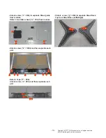
- Unlock screw (“1”: 1EA) to separate Power Cord
bracket from Back cover assembly
And then Separate connector “1-1” from Power
PCB
Separate Dummy Cover(“2”)
- Unlock screw (“3”: 21EA, ”4”: 4EA, “5”: 1EA) to
separate back cover assembly from module.
- Detach Tape (“6”: 3EA, “7”: 3EA, “8”: 8EA
- Separate connectors “9” ~ “19” from PCB
- Unlock screw (“a”: 17EA, “b”: 1EA) to separate
from module.
And then separate Main Chassis & Power Chassis
from module.
And then separate Middle Cabinet Assy from
module
1
1-1
2
7
6
7
6
8
8
8
8
8
7
6
11
9
10
15
16
17
18
13
12
14
19
Summary of Contents for 75SJ857A
Page 59: ......


