


- 14 -
6) Stick sensor to center of the screen and select each items
(Red/Green/Blue Gain and offset) using
D
/
E
(CH +/-) key
on R/C.
7) Adjust Only High Light with R Gain/ B Gain using
F
/
G
(VOL+/-) key on R/C.
8) Adjust it until color coordination becomes as below.
(Initially, R/G/B gain and R/G/B offset values are fixed
Red Gain : 82, Green Gain : 80, Blue Gain : 86
Red Offset : 7D, Green Offset : 7E, Blue Offset : 80)
(High Light G Gain : 7A // Low Light R Offset : 7F, G Offset
7E, B Offset 80 is Fixed)
Bright :
High Light : 80 ± 20cd
Color-Coordinate :
High Light : X : 0.285 ± 0.003
Y : 0.295 ± 0.003
Color Temperature : 9,300°K ± 500°K
9) When adjustment is completed, Exit adjustment mode using
EXIT key on R/C
8. Auto Component Color Balance
[Requirement]
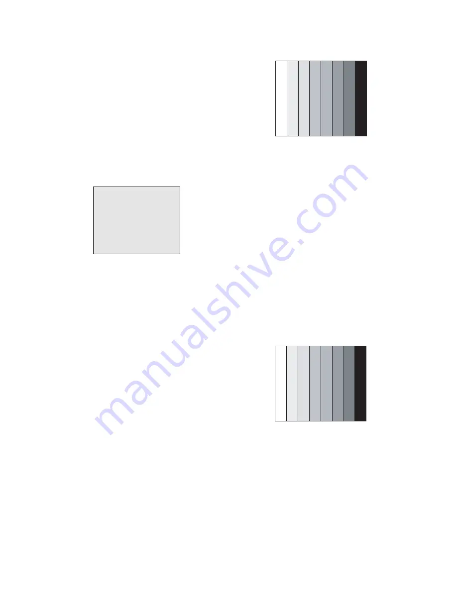
It is very import to use correct adjustment pattern like fig.9
V
Within the pattern, color sequence should be aligned
: W-Y-C-G-M-R-BLUE-BLACK
(If color sequence is reversed(Black -> ... > White), reverse
the pattern with REV key, when using Master pattern
generator like MSPG-925)
V
If Minimum Black Level and/or Maximum White Level is not
correct, Select 100% Color Bar Pattern.
8-1. Required Test Equipment
1) Remote controller for adjustment
2) 802F Pattern Generator
(Which has 720p Ypbpr output & PC 1024x768 60Hz with
Standard(0.7Vpp) Vertical 100% Color Bar Pattern as Fig.9)
8-2. Method of Auto Component Color Balance
1) Input the Component 720p 100% Color Bar signal into
Component1 or Component2.
2) Set the PSM to Standard mode in Picture menu.
3) Press INSTART key on R/C for adjustment.
4) Press the
G
(Vol. +) key operate To set, then it becomes
automatically.
5) Auto-RGB OK means complete adjustment
9. Auto RGB Color Balance
[Requirement]
It is very import to use correct adjustment pattern like fig.10
V
Within the pattern, color sequence should be aligned
: W-Y-C-G-M-R-BLUE-BLACK
(If color sequence is reversed(Black -> ... > White), reverse
the pattern with REV key, when using Master pattern
generator like MSPG-925)
V
If Minimum Black Level and/or Maximum White Level is not
correct, Select 100% Color Bar Pattern.
9-1. Required Test Equipment
1) Remote controller for adjustment
2) 802F Pattern Generator
(Which has VGA 60Hz PC Format output with standard
(0.7Vpp) Vertical 16 Gray Scale pattern as Fig.10)
9-2. Method of Auto RGB Color Balance
1) Input the PC 1024x768 60Hz 100%Color bar into RGB.
2) Set the PSM to Standard mode in Picture menu.
3) Press ADJ key on R/C for adjustment.
4) Press the
G
(Vol. +) key operate To set, then it becomes
automatically.
5) Auto-RGB OK means completed adjustment.
(Fig. 10) Auto RGB Color Balance Test Pattern
(Fig. 9) Auto Component Color Balance Test Pattern
(Fig. 8) Pattern for Adjustment of White Balance
216 Level (85 IRE)
Summary of Contents for 60PZ9M/MA
Page 25: ...PRINTED CIRCUIT BOARD 25 MAIN TOP ...
Page 26: ... 26 MAIN BOTTOM POWER S W ...
Page 27: ... 27 A V TOP A V BOTTOM CONTROL BOTTOM CONTROL TOP ...
Page 28: ... 28 BLOCK DIAGRAM Wired IR AT24C02 AT24C02 HUD_HS VS DE CLK OR OR Scart Block Diagram OUT PUT ...
Page 29: ... 29 Variable_audio_out LR RCA Block Diagram HUD_HS VS DE CLK OR OR ...
Page 36: ......
Page 37: ......
Page 38: ......
Page 39: ......


