- 6 -
1.
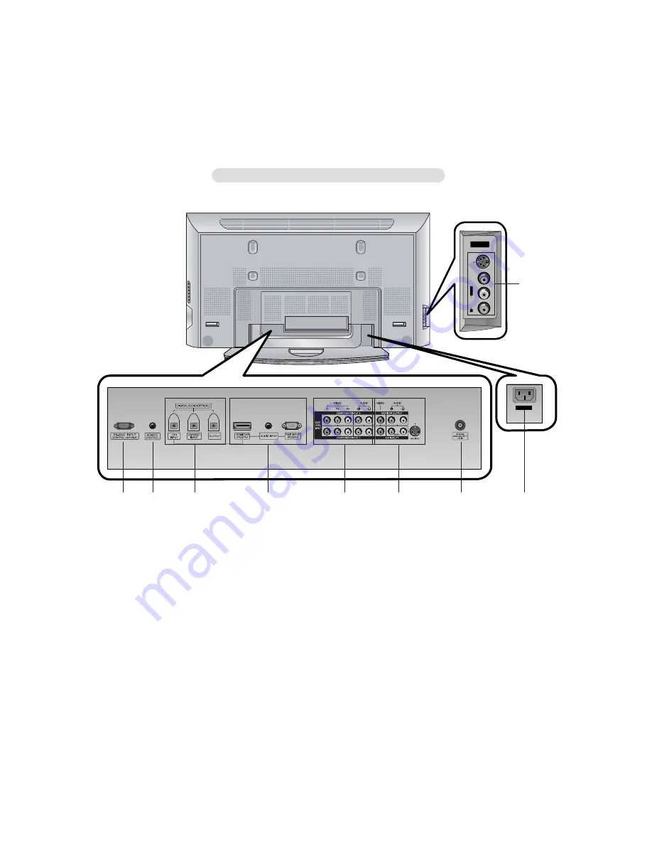
RS-232C INPUT (CONTROL/SERVICE) PORT
Connect to the RS-232C port on a PC.
2.
CONTROL LOCK / REMOTE CONTROL
3.
DVI INPUT/COMPONENT 1 INPUT/OUTPUT (DIGITAL
AUDIO (OPTICAL))
Connect digital audio from various types of equipment.
Note: In standby mode, these ports will not work.
4.
HDMI/DVI INPUT / AUDIO INPUT / RGB INPUT (PC/DTV)
Connect the monitor output socket of the PERSONAL COM-
PUTER to this socket.
Note: If you want to use RGB/DVI audio, we strongly rec-
ommend that you use the cable that has a core, or the EMI
Filter core along with separate cable.
5.
COMPONENT INPUT
Connect DVD video outputs to Y, P
B
, P
R
of COMPONENT
INPUT and audio outputs to Audio sockets of AUDIO INPUT.
6.
AUDIO/VIDEO IN SOCKETS (A/V INPUT1)
Connect the audio/video out sockets of external equipment
to these sockets.
S-VIDEO/AUDIO IN SOCKETS
Connect the S-VIDEO out socket of the VCR to the S-VIDEO
socket.
Connect the audio out sockets of the VCR to the audio sock-
ets as in A/V INPUT1.
AUDIO/VIDEO OUT SOCKETS (MONITOR OUTPUT)
7.
ANTENNA INPUT
8.
POWER CORD SOCKET
This Monitor operates on AC power. The voltage is indicated
on the Specifications page. Never attempt to operate the
Monitor on DC power.
9.
AUDIO/VIDEO IN SOCKETS (A/V INPUT2)
S-VIDEO/AUDIO IN SOCKETS
S
-V
ID
E
O
V
ID
E
O
A
U
D
IO
R
L/
M
O
N
O
A/V INPUT2
A/V INPUT2
AC INPUT
1
9
2
3
4
5
6
7
8
<Back Panel>
Summary of Contents for 60PY2D
Page 20: ...PRINTED CIRCUIT BOARD 20 MAIN TOP ...
Page 21: ... 21 MAIN BOTTOM ...
Page 22: ... 22 TUNER TOP ...
Page 23: ... 23 TUNER BOTTOM ...
Page 24: ... 24 EPF BOTTOM CONTROL EPF TOP ...
Page 25: ... 25 SIDE A V TOP SIDE A V BOTTOM AUDIO LED FAN EXT RIGHT FAN EXT LEFT ...
Page 26: ... 26 BLOCK DIAGRAM ...
Page 27: ... 27 ...
Page 37: ......
Page 38: ......
Page 39: ......
Page 40: ......


