


- 6 -
LGE Internal Use Only
Copyright©2008 LG Electronics. Inc. All right reserved.
Only for training and service purposes
ADJUSTMENT INSTRUCTION
1. Application Object
These instructions are applied all of the 50” PLASMA TV,
PE81A
Chassis.
2. Note
(1) Because this is not a hot chassis, it is not necessary to use
an isolation transformer. However, the use of isolation
transformer will help protect test instrument.
(2) Adjustment must be done in the correct order.
(3) The adjustment must be performed in the circumstance of
25±5°C of temperature and 65±10% of relative humidity if
there is no specific designation.
(4) The input voltage of the receiver must keep 100-240V~,
50/60Hz.
(5) The receiver must be operated for about 5 minutes prior to
the adjustment.
O
After RGB Full white HEAT-RUN Mode, the receiver must
be operated prior to adjustment.
O
Enter into HEAT-RUN MODE
1) Press the POWER ON KEY on R/C for adjustment.
2) OSD display and screen display PATTERN MODE.
* Set is activated HEAT-RUN without signal generator in
this mode.
* Single color pattern(RED/BLUE/GREEN) of HEAT-RUN
mode uses to check PANEL.
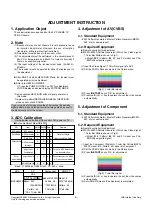
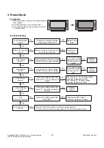
3. ADC Calibration
V
Auto adjustment Map(RS-232C)
- Baud : 115200bps, RS232 Host : PC, Echo : none.
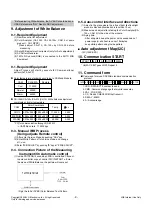
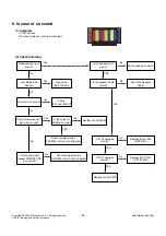
4. Adjustment of AV(CVBS)
4-1. Standard Equipment
: 802F Pattern Generatorr. Master Pattern Generator(MSPG-
925, etc) or same product.
4-2. Required Equipment
O
Remote controller for adjustment.
O
MSPG-925FS Pattern Generator. (Which has Video Signal:
7 Color Bar Pattern shown in Fig.1)
-> Model:
202
/ Pattern:
65
EC and FC model use PAL-
BGDHI(composite signal)
(1) Input the Video Signal: 7 Color Bar signal into AV3.
(2) Set the PSM to Dynamic mode in the Picture menu.
(3) Press
IN-START
key on R/C for adjustment.
(4) Press the
G
(Vol. +) key to operate the set, then it becomes
automatically.
5. Adjustment of Component
5-1. Standard Equipment
: 802F Pattern Generatorr. Master Pattern Generator(MSPG-
925, etc) or same product.
5-2. Required Equipment
O
Remote controller for adjustment.
O
MSPG-925FS Pattern Generator. (Which has Video Signal:
7 Color Bar Pattern shown in Fig.2)
-> Model:
215
/ Pattern:
65
EC and FC model use PAL-
BGDHI(composite signal)
(1) Input the Component 720p/50Hz 7 color Bar Pattern(MSPG-
925FS model : 215, Pattern : 65) signal into Component.
(2) Set the PSM to Dynamic mode in the Picture menu.
(3) Press
IN-START
key on R/C for adjustment.
(4) Press the
G
(Vol. +) key to operate the set, then it becomes
automatically.
(5) Auto-RGB OK means the adjustment is completed.
* Using ‘power on’ button off the control R/C, power on TV.
If you turn on a still screen more than 20 minutes, (Especially
digital pattern, cross hatch pattern) after image may be occur in
the black level part of the screen.
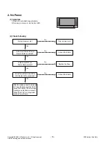
ADC adjust
Data Read
Default Write
Enter
Adjust Mode
ADC adjust
ADC Parameter
Digital Data
ADC Parameter
(Average)
Adjustment
Confirmation
Adjust Mode In
Adjust Mode Off
NO
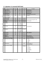
Item
Remark
CMD1 CMD2 Data 0
A
A
A
A
A
A
A
D
D
D
D
D
D
D
0
0
0
0
9
0
0
1
2
3
4
9
0
9
Transfer 18Byte
(Input resolution Data)
To check ADC Adjusment
on Assembly line
When transger the ‘Mode
In’, Carry the command.
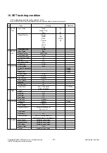
MSPG925FS
Component
RGB-PC
AV
ADC
Model : 3
(1024*768 60Hz)
Pattern : 65
7 Color Bar
Model:215(720P)
Pattern : 65
* 720P/50Hz
7 Color Bar
PAL
INPUT SELECT AV3
Model : 202
(PAL-BGDHI)
Pattern : 65
* PAL 7 Color Bar
(Fig.1) 7 color Bar signal
(Fig.2) 7 color Bar signal


