- 10 -
4. Video(uPD)-Set
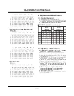
Adjustment for reduce color difference Main/Sub screen of RF
or Video signal.
4-1. Adjustment
(1) Connection the Video Signal Generator(Master) to the
Video Input terminal of TV AV1.
After input pattern(Model: 201(NTSC-M), Pattern: 32(100%
color Bar), pressing the ‘Rev’ button and appear as below
figure
(2) Check receiving the RF signal at the Antenna Input.
And Enter the ‘EZ-ADJUST’ by pressing the ADJ Key on
the Service R/C.
Select ‘4. Video(UPD)-Set’ and enter the adjustment mode
by pressing the right key (
G
).
(3) When enter the adjustment mode, displayed is the 2CH
SPLIT will appear as the image below.
(4) When the automatic adjustment is over, 'RF Configuration
Success’ is displayed. If the adjustment has errors, 'Video
Configuration Error’ is displayed.
(5) After the RF signal automatic adjustment is over, convert
the Video Mode as below figure and adjust with automatic
movement the Video Mode.
When the automatic adjustment is over, 'Video
Configuration Success’ is displayed. If the adjustment has
errors, 'Video Configuration Error’ is displayed.
5. EPLD Download
(1) Test Equipment: PC, Jig for download
(2) Connect the power of VSC B/D.
(3) Execute download program(iMPACK) of PC.
(4) After executing the hot key on the Programmer, click icon
(5) End after confirming
ADJUSTMENT INSTRUCTIONS
Model: 201(NTSC-M), Pattern: 32(100% color Bar)
PC
VSC
B/D
Connection Diagram of EPLD Download
Summary of Contents for 42PX7DC
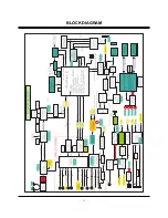
Page 15: ... 15 BLOCK DIAGRAM ...
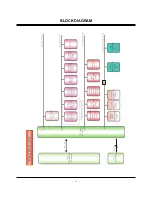
Page 16: ... 16 BLOCK DIAGRAM ...
Page 17: ... 17 BLOCK DIAGRAM ...
Page 48: ......
Page 49: ......
Page 50: ......


