background image

Owner’s Manual   17

Installation

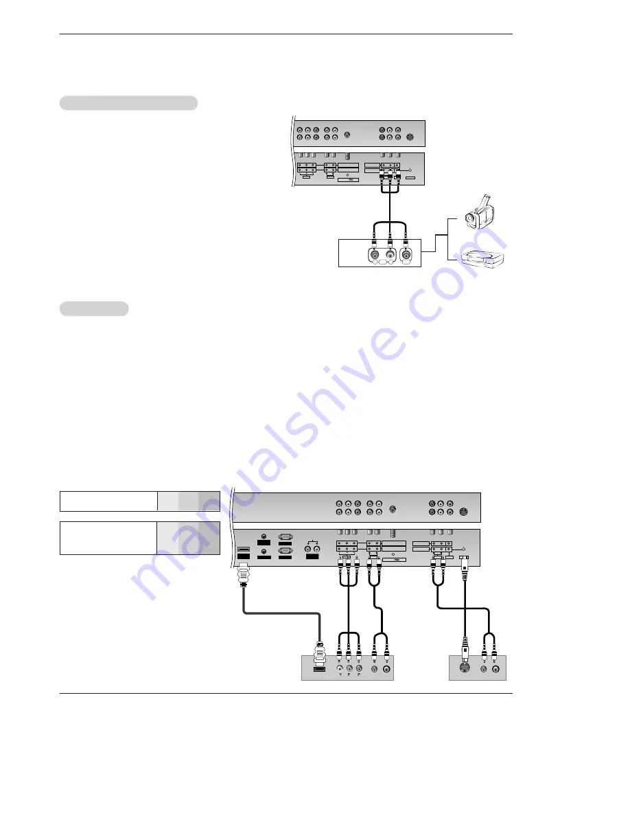
Component Input ports

To get better picture quality, connect a DVD player to the compo-
nent input ports as shown below.

How to connect

Connect the audio and video cables from the external
equipment's output jacks to the TV input jacks, as shown in
the figure. 
When connecting the TV to external equipment, match the
jack colors (Video = yellow, Audio Left = white, and Audio
Right = red).

How to use

1. Select the input source with using the 

TV/VIDEO

button on

the remote control. (If connected to A/V INPUT 1, select

Video 1 

input source).

2. Operate the corresponding external equipment. Refer to

external equipment operating guide.

Component ports 

on the TV

Y

P

B

P

R

Video output ports 
on DVD player

Y
Y
Y
Y

Pb

B-Y

Cb

P

B

Pr

R-Y

Cr

P

R

How to connect

1. Connect the DVD video outputs (Y, P

B

, P

R

) to the COMPONENT (Y, P

B

, P

R

) INPUT or HDMI INPUT jacks on the TV and con-

nect the DVD audio outputs to the AUDIO INPUT jacks on the TV, as shown in the figure.

2. If your DVD only has an S-Video output jack, connect this to the S-VIDEO input on the TV and connect the DVD audio outputs

to the AUDIO INPUT jacks on the TV, as shown in the figure.

NOTE: 

If your DVD player does not have component video output, use S-Video.

How to use

1. Turn on the DVD player, insert a DVD.
2. Use the 

TV/VIDEO

button on the remote control to select 

Component 1 

or 

Component 2

. (If connected to S-VIDEO, select the

Video 1 

or 

Video 2

external input source.)

3. Refer to the DVD player's manual for operating instructions.

External 

External 

A/V Source Setup

A/V Source Setup

DVD Setup

DVD Setup

AUDIO 

VARIABLE 
AUDIO OUT

Antenna

S-VIDEO

COMPONENT INPUT 2

COMPONENT INPUT 1

AUDIO

VIDEO

R

L

AUDIO

VIDEO

R

MONITOR OUT

A/V INPUT

L

MONO

R

L

AUDIO

VIDEO

AUDIO 

AUDIO 

L

R

 REMOTE
CONTROL

AUDIO INPUT

RGB INPUT

VARIABLE 

ARIABLE 

AUDIO OUT

AUDIO OUT

     HDMI/
DVI(VIDEO)

RGB OUTPUT

Antenna

S-VIDEO

COMPONENT INPUT 2

COMPONENT INPUT 1

AUDIO

VIDEO

R

L

AUDIO

VIDEO

R

MONITOR OUT

A/V INPUT

L

MONO

B

R

(R) AUDIO (L)

(R) AUDIO (L)

S-VIDEO

HDMI OUTPUT

DVD

or

Camcorder

Video Game Set

Summary of Contents for 42PX4RV series

Page 1: ...tain this manual for future reference Record model number and serial number of the TV in the spaces provided below See the label attached on the back cover and relate this information to your dealer if you require service Model Number Serial Number MODELS 42PX4RV 50PX5R 42PX4RV UC 42PX4RV MC 50PX5R UC ...

Page 2: ...tions may cause harmful interference to radio communications However there is no guarantee that interference will not occur in a particular installation If this equipment does cause harmful interference to radio or television reception which can be determined by turning the equipment off and on the user is encouraged to try to correct the interference by one or more of the following measures Reori...

Page 3: ...ollow all instructions 5 Do not use this apparatus near water 6 Clean only with dry cloth 7 Do not block any ventilation openings Install in accordance with the manufacturer s instructions 8 Do not install near any heat sources such as radiators heat registers stoves or other apparatus including ampli fiers that produce heat 9 Do not defeat the safety purpose of the polarized or grounding type plu...

Page 4: ...ound Menu Options DASP Digital Auto Sound Processing 26 BBE 26 AVL Auto Volume Leveler 26 Manual Sound Control User option 27 TV speaker Setup 27 Stereo SAP Broadcasts Setup 27 Timer Menu Options Clock Setup 28 On Off Timer Setup 28 Auto Off Sleep Timer 28 Special Menu Options Key Lock 29 ISM Image Sticking Minimization Method 29 Low Power 30 XD Demo 30 Closed Captions 31 Caption Text 31 Screen Me...

Page 5: ...sma display to a PC and you can use it for conferencing games and Internet browsing The Picture in Picture feature allows you to view your PC and video images simultaneously Versatile The light weight and thin size makes it easy to install your plasma display in a variety of locations where conventional TVs will not fit The PDP Manufacturing Process a few minute colored dots may be present on the ...

Page 6: ...te Control Sensor 3 TV VIDEO Button Selects the TV VIDEO Component RGB or HDMI modes Switches the set on from standby 4 MENU Displays on screen menus one by one Exits the current menu Memorizes menu changes 5 ENTER Accepts your selection or displays the current mode 6 D D E E Programme Up Down Selects a programme or a menu item Switches the set on from standby F F G G Volume Up Down Adjusts the vo...

Page 7: ... signal 3 REMOTE CONTROL AUDIO INPUT for RGB DVI 4 RGB INPUT RGB OUTPUT Connect to the RS 232C port on a PC 5 VARIABLE AUDIO OUTPUT 6 COMPONENT INPUT Connect DVD video outputs to Y PB PR of COMPONENT INPUT and audio outputs to Audio sockets of AUDIO INPUT 7 ANTENNA INPUT 8 VIDEO AUDIO IN OUT SOCKETS AV1 Connect the video audio out sockets of external equipment to these sockets S VIDEO AUDIO IN SOC...

Page 8: ...RD button is not available for DVD player CAPTION Selects CAPTION mode POWER Turns your TV or any other programmed equipment on or off depending on mode THUMBSTICK Up Down Left Right ENTER Allows you to navigate the on screen menus and adjust the system settings to your pref erence CHANNEL UP DOWN Selects available channels found with Auto program Adjusts menu settings Switches the set on from sta...

Page 9: ...e sub picture in PIP Twin picture mode SWAP Exchanges the main sub images in PIP Twin picture mode SIZE Adjusts the sub picture size POSITION Moves the sub picture in pip mode MODE TV INPUT TV VIDEO ARC ARC Changes the picture format FRC Use to scroll the favorite channel list MEMORY ERASE Memorizes or erases selected channel SLEEP Sets the sleep timer APC Adjusts the factory preset picture accord...

Page 10: ... 1280 x 720p Because HDMI sends Digital Video and Audio with one cable need not especial Audio Cable for using HDMI Cable 2 When Source Devices DVD Player or Set Top Box supports DVI If Source Devices have DVI Output Connector Source Devices connect to the set with HDMI to DVI Cable not supplied with the product If Source Devices support Auto DVI automatically Source Devices divert output resoluti...

Page 11: ...ixed image may become permanently imprinted on the screen Use the Orbiter screen saver when possible When Source Devices connected HDMI DVI Input output PC Resolution VGA SVGA XGA Position Size may not fit to Screen As shown the lower picture press the MENU button to adjust the screen Position of the set and contact an PC graphics card ser vice center When Source Devices connected HDMI DVI Input o...

Page 12: ...feet 1000m to get the best quality picture and sound It is recommended that RP 42PX40H model only be used at an altitude of less than 6561 feet 2000m to get the best quality pic ture and sound GROUNDING Ensure that you connect the grounding earth wire to prevent possible electric shock If grounding methods are not possible have a qualified electrician install a separate circuit breaker Do not try ...

Page 13: ...supplied with the product as shown Match the height of the eye bolts and the wall brackets Check to be sure the eye bolts and the brackets are tightened securely Secure the TV assembly to the wall with strong strings or wound wire cables not supplied with the product as shown 40 42 50 42 40 Ceiling mounting bracket Optional extras can be changed or modified for quality improvement without any noti...

Page 14: ...shown above For further information refer to the optional Wall Mounting Bracket Installation and Setup Guide Swivel function option After installing the set you can adjust the the set manually to the left or right direction by 20 degrees to suit your view ing position Note Before adjusting the angle you must loosen to the left the shaft bolt on the middle of stand s back And when stand be level wi...

Page 15: ...install a 2 Way Signal Splitter in the connections If the antenna is not installed properly contact your dealer for assistance A V INPUT2 Signal Amplifier A V INPUT2 AUDIO VARIABLE AUDIO OUT Antenna COMPONENT INPUT 2 COMPONENT INPUT 1 AUDIO VIDEO R L Multi family Dwellings Apartments Connect to wall antenna socket Single family Dwellings Houses Connect to wall jack for outdoor antenna outdoor ante...

Page 16: ...y the S Video will work VCR Setup VCR Setup AUDIO VARIABLE AUDIO OUT Antenna S VIDEO COMPONENT INPUT 2 COMPONENT INPUT 1 AUDIO VIDEO R L AUDIO VIDEO R MONITOR OUT A V INPUT L MONO S VIDEO OUT IN R AUDIO L VIDEO 3 4 OUTPUT SWITCH ANT OUT ANT IN After subscribing to a cable TV service from a local provider and installing a converter you can watch cable TV programming The TV cannot display TV program...

Page 17: ...UDIO INPUT jacks on the TV as shown in the figure 2 If your DVD only has an S Video output jack connect this to the S VIDEO input on the TV and connect the DVD audio outputs to the AUDIO INPUT jacks on the TV as shown in the figure NOTE If your DVD player does not have component video output use S Video How to use 1 Turn on the DVD player insert a DVD 2 Use the TV VIDEO button on the remote contro...

Page 18: ...MOTE CONTROL AUDIO INPUT RGB INPUT VARIABLE AUDIO OUT HDMI DVI VIDEO RGB OUTPUT Antenna COMPONENT INPUT 2 COMPONENT INPUT 1 AUDIO VIDEO R L B R R AUDIO L Digital Set top Box or or Signal 480i 480p 720p 1080i Component 1 2 Yes Yes Yes Yes RGB HDMI No Yes Yes Yes The TV has a special signal output capability which allows you to hook up a second TV or monitor Connect the second TV or monitor to the T...

Page 19: ... AUDIO OUT AUDIO OUT HDMI DVI VIDEO RGB OUTPUT Antenna COMPONENT INPUT 2 COMPONENT INPUT 1 AUDIO VIDEO R L How to use 1 Turn on the PC and the TV 2 Turn on the display by pressing the POWER button on the TV s remote control 3 Use TV VIDEO on the remote control to select RGB or HDMI source 4 Check the image on your TV There may be noise associated with the resolution vertical pattern contrast or br...

Page 20: ...8 63 995 67 500 68 681 60 023 63 981 RGB HDMI mode 50PX5R series 42PX4RV series Resolution 640x350 720x400 640x480 848x480 800x600 Horizontal Frequency KHz Vertical Frequency Hz 852x480 832x624 1024x768 1360x768 1366x768 1152x864 1152x870 1280x960 1280x768 1280x1024 70 09 85 08 70 08 85 03 59 94 66 66 72 80 75 00 85 00 60 00 70 00 75 00 60 00 70 00 75 00 56 25 RGB 60 31 72 18 75 00 85 06 74 55 60 ...

Page 21: ...all power outlet In this manual the OSD On Screen Display may be different from your TV s because it is just an example to help you with the TV operation Operation Operation When using the remote control aim it at its sensor on the set Turning on the set just after installation Turning on the set power cord is still connected 1 Connect power cord correctly the set is switched to standby mode 2 Pre...

Page 22: ...nal channels you want to add or delete you can manually add or delete those channels with Manual Program Redo Auto Program if the Plasma Display is ever moved to another location Auto Program will search for channels only through the ANT IN jack If channels numbers for broadcast over the air TV and cable TV are duplicated where different channels have the same number press the same number but tons...

Page 23: ... repeatedly The eight favorite channels appear on the screen in numerical order Favorite Channels Setup Favorite Channels Setup If TV signal reception is poor because you are in a fringe area set Booster to On If the picture condition is good set Booster to Off Adjustments for one channel don t affect the adjustment for other channels Set booster to on or off for each channel separately 1 Press th...

Page 24: ...ature Control To initialize values reset to default settings select the Normal option 1 Press the MENU button and then use D E button to select the PICTURE menu 2 Press the G button and then use D E button to select ACC 3 Press the G button and then use D E button to select either Cool Preset Normal Default or Warm Preset 4 Press the ENTER button to save Color Color T Temperature Control emperatur...

Page 25: ... 3 Press the G button and then use D E button to select On or Off 4 Press the ENTER button to save sRGB only RGB PC DVI PC Modes sRGB only RGB PC DVI PC Modes PICTURE Prev APC ACC ACM Contrast 80 G Brightness 60 Color 50 Sharpness 50 Tint 0 PICTURE MENU PICTURE Prev APC ACC ACM G Contrast 80 Brightness 60 Color 50 Sharpness 50 Tint 0 PICTURE MENU Freshtone 0 Greentone 0 Bluetone 0 Adjust the ACM t...

Page 26: ... AVL maintains an equal sound level even if you change channels 1 Press the MENU button and then use D E button to select the SOUND menu 2 Press the G button and then use D E button to select A VL 3 Press the G button and then use D E button to select On or Off 4 Press the ENTER button to save A AVL VL Auto V Auto Volume Leveler olume Leveler 1 Press the MENU button and then use D E button to sele...

Page 27: ...ard from left and right speakers in mono sound 1 Press the MENU button and then use D E button to select the SOUND menu 2 Press the G button and then use D E button to select the desired sound option Balance Treble Bass 3 Press the G button and then use F G button to make appropriate adjustments 4 Press the ENTER button to save Manual Sound Control Manual Sound Control DASP set to set to user opti...

Page 28: ...ton and then use D E button to set the minutes 5 Press the ENTER button to save Auto Of Auto Off f If set to on and there is no input signal the TV turns off automatically after 10 minutes 1 Press the MENU button and then use D E button to select the TIMER menu 2 Press the G button and then use D E button to select Auto off 3 Press the G button and then use D E button to select On or Off 4 Press t...

Page 29: ...age to remain on the TV s screen for a long period of time 1 Press the MENU button and then use D E button to select the SPECIAL menu 2 Press the G button and then use D E button to select ISM Method 3 Press the G button and then use D E button to select either Normal White wash Orbiter or Inversion Normal If image sticking is never a problem ISM is not necessary set to Normal White wash White Was...

Page 30: ...f When you select On the screen darkens 4 Press the ENTER button to save XD Demo XD Demo 1 Press the MENU button and then use D E button to select the SPECIAL menu 2 Press the G button and then use D E button to select Demo 3 Press the G button to begin XD Demo 4 Press the MENU button to stop XD Demo Use it to see the difference between XD Demo on and XD Demo off SPECIAL Prev Language Key lock ISM...

Page 31: ...ion a live program by using a process called real time captioning which creates captions instantly Real time captioning is nor mally done by professional reporters using a machine shorthand system and computer for trans lation into English Captioning is an effective sys tem for the hearing impaired and it can also aid in teaching language skills The picture at left shows a typical caption Caption ...

Page 32: ...t active in HDMI mode 1 Press the MENU button and then use D E button to select the SCREEN menu 2 Press the G button and then use D E button to select Auto config 3 Press the G button to run Auto configure When Auto config has finished OK will be shown on screen If the position of the image is still not correct try Auto adjustment again 4 In RGB PC mode if the image needs to be adjusted more after...

Page 33: ...osition Cinema NR G Reset SCREEN MENU 3D NR 0 MPGE NR 0 Sets up the TV for the best picture appearance for viewing movies 1 Press the MENU button and then use D E button to select the SCREEN menu 2 Press the G button and then use D E button to select Cinema 3 Press the G button and then use D E button to select On or Off 4 Press the ENTER button to save Cinema Mode Setup TV Cinema Mode Setup TV V ...

Page 34: ...e main and sub pictures Selecting an Input Signal Source for PIP Selecting an Input Signal Source for PIP Double W Double Window indow Use the PIP INPUT button to select the input source for the sub picture Each press of PIP INPUT button changes the PIP source Main Picture Sub Picture Main Picture Sub Picture PIP PIP Size Size Press the SIZE button and then use F G button to change the sub picture...

Page 35: ... RS 232C input jack to an external control device such as a computer or an A V control system and control the set s functions externally How to connect external control equipment Connect the serial port of the control device to the RS 232C jack on the Monitor back panel RS 232C connection cables are not supplied with the set The set remote control and front panel controls except main power will no...

Page 36: ...it returns the data of the PC computer Command2 Set ID OK Data x Error Acknowledgement The Monitor transmits ACK acknowledgement based on this format when receiving abnormal data from non viable functions or communication errors Command2 Set ID NG Data x Transmission Receiving Protocol Command Reference List When setting the 23 32 a menu doesn t display on screen Data 1 Illegal Code 2 not support ...

Page 37: ...ol Transmission Data Min 0 Max 64 Refer to Real data mapping 1 See page 40 k f Set ID Data Cr Ack f Set ID OK Data x 07 Contrast Command 2 g G To adjust screen contrast You can also adjust contrast in the PICTURE menu Transmission Data Min 0 Max 64 Refer to Real data mapping 1 See page 40 k g Set ID Data Cr Ack g Set ID OK Data x 08 Brightness Command 2 h G To adjust screen brightness You can also...

Page 38: ...use this mode When main power is on off external control lock is released m Set ID OK Data x 12 OSD Select Command 2 l G To select OSD On Screen Display on off when con trolling remotely Transmission k l Set ID Data Cr Ack Data 0 OSD off 1 OSD on l Set ID OK Data x 14 PIP DW Command 2 n G To control the PIP Picture In picture DW You can also control the PIP DW using the PIP button on the remote co...

Page 39: ...r to Real data mapping 2 See page 40 k Set ID Data Cr Ack Set ID OK Data x 23 PIP Input Select Command 2 y G To select input source for sub picture in PIP DW pic ture mode You can also adjust input source for sub picture using PIP INPUT button on remote control Transmission Data 0 RGB 1 HDMI1 2 Video1 3 Video2 4 Component1 5 Component2 6 TV k y Set ID Data Cr Ack y Set ID OK Data x 24 Abnormal Sta...

Page 40: ...control Transmission Data Min 0 Max 20 Refer to Real data mapping 1 j t Set ID Data Cr Ack t Set ID OK Data x 30 Auto Configure Command 1 j Command 2 u G To adjust picture position and minimize image shaking automatically It works only in RGB PC mode Transmission Data 1 To set j u Set ID Data Cr Ack u Set ID OK Data x Real data mapping 1 0 Step 0 A Step 10 Set ID 10 F Step 15 Set ID 15 10 Step 16 ...

Page 41: ... 0 0 0 0 0 0 External Input Data 0 0 0 1 Analog 0 0 1 0 AV 0 1 0 0 Component 0 1 0 1 RGB DTV 0 1 1 0 RGB PC 1 0 0 1 HDMI External Input Input Number Input Number Data 0 0 0 0 Input1 0 0 0 1 Input2 35 Input select Command 1 x Command 2 y G To adjust input source for sub picture in PIP mode Transmission Data Structure MSB LSB 0 x y Set ID Data Cr Ack y Set ID OK Data x 0 0 0 0 0 0 0 External Input D...

Page 42: ...e Data code TC Tf T1 C0 Carrier frequency FCAR 1 TC fOSC 12 Duty ratio T1 TC 1 3 Repeat frame C1 C2 C3 C4 C5 C6 C7 C0 C1 C2 C3 C4 C5 C6 C7 D0 D1 D2 D3 D4 D5 D6 D7 D0 D1 D2 D3 D4 D5 D6 D7 Repeat code 9 ms 4 5 ms 0 55 ms 9 ms 2 25 ms G Bit description G Frame interval Tf The waveform is transmitted as long as a key is depressed Bit 0 Tf Tf Tf 108ms 455KHz 0 56 ms 0 56 ms 1 12 ms Bit 1 2 24 ms How to...

Page 43: ... Selection Discrete IR Code Input COMPONENT2 Selection Discrete IR Code Input DVI Selection Discrete IR Code Input RGB Selection R C Button R C Button R C Button R C Button R C Button R C Button R C Button R C Button R C Button R C Button R C Button R C Button R C Button R C Button R C Button Discrete IR Code Only 4 3 mode Discrete IR Code Only 16 9 mode Discrete IR Code Only Zoom mode R C Button ...

Page 44: ...YMPHONIC 034 TANDY 010 034 TATUNG 039 043 TEAC 034 039 043 TECHNICS 031 033 070 TEKNIKA 019 031 033 034 101 THOMAS 034 TMK 006 TOSHIBA 008 013 042 047 059 082 112 131 TOTEVISION 040 101 UNITECH 040 VECTOR RESEARCH 012 VICTOR 048 VIDEO CONCEPTS 012 034 046 VIDEOSONIC 040 WARDS 003 013 017 024 031 033 034 040 053 054 131 YAMAHA 012 034 039 043 ZENITH 034 048 056 058 072 080 101 Brand Codes Brand Cod...

Page 45: ...EC 185 186 187 KENWOOD 038 050 067 089 170 171 197 206 215 222 KOHEL 030 NAD 045 046 LOTTE 014 016 036 098 100 172 173 174 175 176 177 178 179 180 181 183 201 202 208 213 214 219 223 232 238 240 LXI 103 MAGNAVOX 111 MARANTZ 002 018 020 025 034 041 081 090 097 112 MCINTOSH 049 MCS 104 MEMOREX 107 NAD 046 ONKYO 013 040 041 047 048 056 057 132 133 140 OPTIMUS 158 PANASONIC 007 033 064 113 142 220 241...

Page 46: ...tween the TV and the VCR Activate any function to restore the brightness of the picture If still picture is on the screen for more than 5 minutes the screen gets dark The remote control doesn t work Check to see if there is any object between the TV and the remote control causing obstruction Are batteries installed with correct polarity to to Refer to p 8 Correct remote operating mode set TV VCR e...

Page 47: ...Depth inches mm Weight pounds kg Resolution Power requirement Television System Program Coverage External Antenna Impedance Color Operating Temperature Range Operating Humidity Range MODELS 50PX5R UC 55 1 1400 32 3 821 3 9 99 115 52 15 1366 x 768 Dot AC100 240V 50 60Hz NTSC PAL M N VHF 2 13 UHF 14 69 CATV 1 125 75 Ω 16 770 000 256 steps of each R G and B 32 104 F 0 40 C Less than 80 Width inches m...

Page 48: ...48 Plasma TV Notes Notes ...

Page 49: ...Owner s Manual 49 Notes Notes ...

Page 50: ...50 Plasma TV Notes Notes ...

Page 51: ...OR OTHERWISE Some states do not allow the exclusion or limitation of incidental or consequential damages or limitations on how long an implied warranty lasts so the above exclusion or limitation may not apply to you This warranty gives you specific legal rights and you may also have other rights that vary from state to state WARRANTY PERIOD LABOR and PARTS 2 YEARS from the Date of Purchase Your un...

Page 52: ...re returning any product to the LGE Service Center Contact the Customer Interactive Center for details CUSTOMER INTERACTIVE CENTER NUMBERS To obtain customer assistance product information or Dealer or Service locations Call 1 800 243 0000 24 hours a day 365 days per year THIS LIMITED WARRANTY DOES NOT APPLY TO The cost of repair or replacement under these excluded circumstances shall be borne by ...

Reviews: