4. PCB Assembly Adjustment Method
4-1. Option Adjustment Following BOM
Tool Option
Area Option
Option 1
Option 2
Option 3(Available for EU & Non EU model)
* Profile: Must be changed the option value because being
different with some setting value depend on module, inch
and market
* Equipment : Adjustment Remote Controller
(1) Push the IN-START key in the Adjust R/C.
(2) Enter Password number. The value of Password is “0 0 0
0”.
(3) Input the Option Number that was specified in the BOM,
into the Shipping area.
(4) Select “Tool Option/ Area Option” by using
D
/
E
(CH+/-) key,
and press the number key(0~9) consecutively
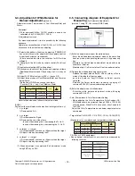
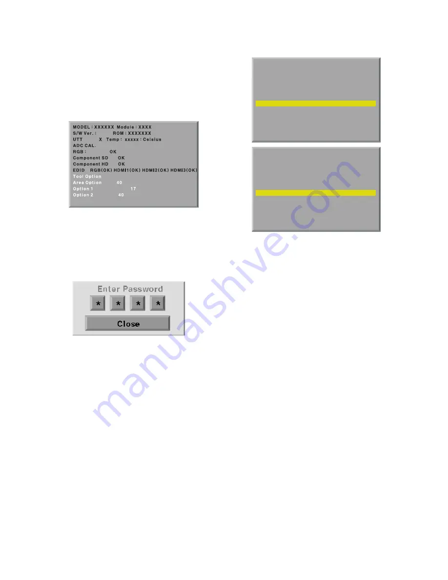
ex) If the value of Tool Option1 is 4, input the data using
number key “4” (Fig. 3)
Caution: Don’t Push “IN-STOP” key after PCB assembly
adjustment.
(5) EDID D/L Method
After software D/L or PCBA manufacturing, you can
download EDID Data.
When you adjust Tool Option, H6 Model EDID download
process is executed automatically
* If the model don’t have HDMI 3, HDMI 3 will be disappeared
at OSD Window.
Caution: When you adjust tool option, don’t connect HDMI or D-
sub cable.
If you connect some cable, EDID D/L process will be
failed.
(6) Adjustment method
Before PCBA check, have to change the Tool option and Area
option
* About PDP
After done all adjustments, Press IN-START button and
compare Tool option and Area option value with its BOM, if it
is correctly same then Change “RF mode” and then unplug
the AC cable.
If it is not same, then correct it same with BOM and unplug AC
cable.
For correct it to the model’s module from factory JIG model.
* Don’t push The IN-STOP KEY after completing the function
inspection.
- 9 -
LGE Internal Use Only
Copyright ©2009 LG Electronics. Inc. All right reserved.
Only for training and service purposes
..
3.09
5
..
MODEL : XXXXXX Module : XXXX
S/W Ver. : X.XX ROM : XXXXXXX
UTT X Temp : xxxxx : Celsius
ADC CAL.
RGB :VV
OK
Component SDV
OK
Component HDV
OK
EDID RGB(OK) HDMI1(NG) HDMI2(NG) HDMI3(NG)
Tool OptionV V
4
Area OptionV V
40V
Option 1V
17
Option 2V
40
..
MODEL : XXXXXX Module : XXXX
S/W Ver. : X.XX ROM : XXXXXXX
UTT X Temp : xxxxx : Celsius
ADC CAL.
RGB :VV
OK
Component SDV
OK
Component HDV
OK
EDID RGB(OK) HDMI1(OK) HDMI2(OK) HDMI3(OK)
Tool OptionV V
4
Area OptionV V
40V
Option 1V
17
Option 2V
40
( Fig. 3)


