background image

- 31 -

BLOCK DIAGRAM

SIF from TUNER

CXA2069

Side AV

V,LR

Rear AV

V, LR

Rear S

YC, LR

Side S

YC, LR

IN1

IN4

IN1

IN4

IN3

IN4

Comp_1

LR

Comp_2

LR

RGB(Phone)

LR

OUT1/R

OUT1/L

ANT/ Cable

TUNER

AUDIO ADC

(CS5331)

Audio R

I2S_SCK_IN 

Audio L

BCM3550

SIF

I2S_LRCH_IN 

I2S_LRCK_IN 

I2S_SCK_IN 

I2S_LRCH_IN 

I2S_LRCK_IN 

SPDIF_IN_P 

SPDIF from MST3361 

_R

MNT_Out

AUDIO DAC

(CS4344)

I2S_SCK_OUT

I2S_LRCH_OUT

I2S_LRCK_OUT

I2S_SCK_OUT

I2S_LRCH_OUT 

I2S_LRCK_OUT 

_L

MNT_Out

Analog L_OUT

Audio

AMP

(TPA3100)

SPDIF Out

SPDIF_OUT_P 

AUD_LEFT_P

AUD_LEFT_N

AUD_RIGHT_N

AUD_RIGHT_P

SPK_L_P

SPK_L_N

SPK_R_N

SPK_R_P

Analog R_OUT

MC3307

(OP-AMP)

IF_P  from TUNER  for DTV

IF_N  from TUNER for DTV

IF_P

IF_N

Summary of Contents for 42PC5D Series

Page 1: ...L CAUTION BEFORE SERVICING THE CHASSIS READ THE SAFETY PRECAUTIONS IN THIS MANUAL CHASSIS PA 73E MODEL 50PC5DC 50PC5DC UC MODEL 50PC5D 50PC5D UC CANADA http biz lgservice com USA http www lgservice com http biz lgservice com ...

Page 2: ...to the AC plug prongs tied together and touch other ohm meter lead in turn to each exposed metallic parts such as antenna terminals phone jacks etc If the exposed metallic part has a return path to the chassis the measured resistance should be between 1MΩ and 5 2MΩ When the exposed metal has no return path to the chassis the reading must be infinite An other abnormality exists that must be correct...

Page 3: ...ROLS 4 SPECIFICATIONS 8 ADJUSTMENT INSTRUCTIONS 9 TROUBLESHOOTING GUIDE 19 PRINTED CIRCUIT BOARDS 24 BLOCK DIAGRAM 27 EXPLODED VIEW 32 EXPLODED VIEW PARTS LIST 33 REPLACEMENT PARTS LIST 34 SCHEMATIC DIAGRAM TABLE OF CONTENTS ...

Page 4: ...U INPUT ENTER Power Standby Indicator Illuminates red in standby mode When the TV is turned on the indica tor blinks green and then illuminates green before the picture is displayed Remote Control Sensor POWE R Button INPUT Button MENU Button ENTER Button VOLUME F G Buttons CHANNEL E D Buttons Plasma TV Model DESCRIPTION OF CONTROLS ...

Page 5: ...ut AUDIO Input VIDEO Input Connects the video signal from a video device R HDMI IN HDMI DVI IN VIDEO AUDIO VIDEO AUDIO MONO S VIDEO ANTENNA CABLE IN REMOTE CONTROL IN RS 232C IN CONTROL SERVICE RGB IN PC AUDIO IN RGB DVI DIGITAL AUDIO OUT OPTICAL 1 2 SERVICE COMPONENT IN AV OUT AV IN 1 2 1 8 3 7 6 9 5 Plasma TV Model 4 11 10 DESCRIPTION OF CONTROLS ...

Page 6: ...corders or DVD players Displays the main menu Adjust the brightness on screen Navigate the on screen menus and adjust the sys tem settings to your preference Clear all on screen displays and return to TV view ing from any menu Select the amount of time before your TV turns off automatically Change the aspect ratio C Increase decrease the sound level Switch the sound on or off Scroll through the pr...

Page 7: ...1 2 RGB PC HDMI1 DVI and HDMI2 AV 1 2 Component 1 2 RGB PC HDMI1 DVI and HDMI2 input sources are linked automatically only if a device is connected PICTURE SOUND SAP CC ADJUST Selects the factory preset picture depend on the viewing environment Selects the factory preset sound for type of program Analog mode Selects MTS sound Mono Stereo or a SAP DTV mode Changes the audio language Select a closed...

Page 8: ...2 6 x 3 5 inches 1242 0 x 827 2 x 88 0 mm 86 6 pounds 39 3 kg 76 3 pounds 34 6 kg AC100 240V 50 60Hz NTSC M ATSC 64 256 QAM VHF 2 13 UHF 14 69 CATV 1 135 DTV 2 69 CADTV 1 135 75 ohm 32 104 F 0 40 C Less than 80 4 140 F 20 60 C Less than 85 Dimensions Width x Height x Depth Weight Power requirement Television System Program Coverage External Antenna Impedance Environment condition Including stand E...

Page 9: ...ge detection and 100 FULL WHITE PATTERN must be operated automatically 1 Pressing Power On key 2 Full Test Pattern 2 min 30sec 3 Full Black Pattern 30sec 4 Full White Pattern O Pattern Mode is deselected by pressing CH Exit Key Set is activated HEAT RUN without signal generator in this mode 3 MICOM Download Option 3 1 Required Test Equipment 1 JIG LEVER TYPE for adjusting 1EA 2 PC MONITOR 2EA 3 BO...

Page 10: ...on Auto Write Verity Jig Option Myson Transmit Speed Medium 3 Check Just do it with blank micom 4 PORT Chose Parallel Port normal LPT1 Attention You must chose EPP when select Rom BIAS at LPT 3 5 Download Method 1 Click the Load File 2 Locate and select the correct file from your computer hex 3 Click the Send 4 When you see ISP COMPLETE the download is complete ...

Page 11: ...ion Press Enter on the remote controller to confirm the upgrade 4 The following picture shows the downloading in progress Once the download is completed the power is automatically turned on and off Otherwise please turn the power on and off 5 Once the download is completed remove the USB memory stick from the USB port Press IN START on the remote controller to check the upgraded S W version at the...

Page 12: ...panel Deviation 0 5V 2 Vs Adjustment 1 Connect terminal of D M M to Vs pin of P12 and connect terminal to GND pin of P12 2 Adjust VR901 voltage to match that of the label on the Top Right of the panel Deviation 0 5V Each PCB Assy must be checked by Check JIG Set before assembly Especially be careful Power PCB Assy which can cause Damage to the PDP Module 1 1 1 VsADJ VR951 VaADJ VR901 3 3V ADJ VR22...

Page 13: ...e to match that of the label on the Top Right of the panel Deviation 0 5V 6 ADC Set Adjustment 6 1 Synopsis ADC Set adjustment to set the black level and the Gain to optimum 6 2 Test Equipment Service R C 801GF 802V 802F 802R or MSPG925FA Pattern Generator 480i 1080i The Horizontal 100 Color Bar Pattern adjust to within 0 7 0 1Vp p ADC adjustment MSPG 925Fx series Model No Pattern No Model No 209 ...

Page 14: ...F __________________________________________________ 0 00 FF FF FF FF FF FF 00 1E 6D 01 00 01 01 01 01 10 00 10 01 03 80 73 41 96 0A CF 74 A3 57 4C B0 23 20 09 48 4C 2F CE 00 31 40 45 40 61 40 01 01 01 01 30 01 01 01 01 01 01 66 21 50 B0 51 00 1B 30 40 70 40 36 00 C4 8E 21 00 00 1E 0E 1F 00 80 51 00 1E 30 50 40 80 37 00 C4 8E 21 00 00 1C 00 00 00 FD 00 38 60 4B 1F 3C 09 00 0A 20 20 20 20 02 20 00 ...

Page 15: ...00 00 18 00 00 00 60 00 00 00 00 00 00 00 00 00 00 00 00 00 00 00 00 70 00 00 00 00 00 00 00 00 00 00 00 00 00 00 00 A7 EDID for HDMI 2 DDC Display Data Channel Data EDID Block 0 table 0 1 2 3 4 5 6 7 8 9 A B C D E F ___________________________________________________ 0 00 FF FF FF FF FF FF 00 1E 6D 01 00 01 01 01 01 10 00 10 01 03 80 73 41 96 0A CF 74 A3 57 4C B0 23 20 09 48 4C 2F CE 00 31 40 45 ...

Page 16: ...ontroller to start Ez Adjust and then selects 6 White Balance Requirements for Automatic Adjustment 1 The illuminance of surroundings 10 lux or less preventing light in surroundings as much as possible 2 The location of the Probe 1 For PDP place the color analyzer CA 100 CA 100 and CA 210 close to the surface of a module and start the adjustment 2 For LCD place the color analyzer CA 210 close to t...

Page 17: ...rface when you adjust 4 Select 6 White Balance of Ez Adjust by pressing the ADJ KEY on the Service R C Then enter adjustment mode by pressing the Right KEY G The internal pattern of full white appears by pressing G 5 The adjustment is conducted in three levels of color temperature COOL MEDIUM and WARM WARNING RGB Cut fixed value If the model has a fixed value the equivalent value must be applied C...

Page 18: ...1 Glass 50 WXGA 50X4 Temp uv Color Coordination Cool Medium Warm Cool Medium Warm 11200K 9400K 6500K 11100K 9400K 6500K 0 002 0 002 0 002 0 001 0 002 0 001 x 0 276 0 002 0 285 0 002 0 314 0 002 0 276 0 002 0 285 0 002 0 314 0 002 y 0 280 0 002 0 290 0 002 0 321 0 002 0 281 0 002 0 291 0 002 0 322 0 002 Module Maker Filter Mode 42 XGA 42X3 50 WXGA 50X4 41 Glass Filter This model can be adjusted by ...

Page 19: ...the input PinH26 of BCM3550 IC4006 Measure waveform at C1010 because it s more easy to check Can you see the normal waveform YES YES NO You should check power line IIC lines YES You should replace TUNER NO After checking the Power of AV switch you should decide to replace AV switch or not NO After checking the Power of AV switch you should decide to replace AV switch or not NO After checking the P...

Page 20: ... you see the normal waveform YES Check the input PinH26 of BCM3550 IC4006 Measure waveform at C1010 because it s more easy to check Can you see the normal waveform YES YES NO After checking the Power of AV switch you should decide to replace AV switch or not NO After checking the Power of AV switch you should decide to replace AV switch or not NO After checking the Power of LPF you should decide t...

Page 21: ...form YES Check the input and output of BCM3550 IC4006 Especially you should check The H V sync and clock Can you see the normal waveform YES YES NO After checking the input TR of component you should decide to replace component switch or not NO NO After checking the Power of MST3361 you should decide to replace MST3361 or not NO This board has big problem because Main chip BCM3550 have some troubl...

Page 22: ...rm YES Check the input and output of BCM3550 IC4006 Especially you should check The H V sync and clock Can you see the normal waveform YES YES NO After checking the input TR of RGBHV you should decide to replace these components or not NO NO After checking the Power of MST3361 you should decide to replace MST3361 or not NO This board has big problem because Main chip BCM3550 have some troubles Aft...

Page 23: ...ck The H V sync and clock Can you see the normal waveform YES YES NO NO After checking the trace of TMDS lines and power of MST3361 you should decide to replace MST3361 or not NO This board has big problem because Main chip BCM3550 have some troubles After checking thoroughly all path once again You should decide to replace BCM3550 or not After checking the Power of this chip you should decide to ...

Page 24: ... 24 PRINTED CIRCUIT BOARDS MAIN TOP ...

Page 25: ... 25 PRINTED CIRCUIT BOARDS MAIN BOTTOM ...

Page 26: ... 26 PRINTED CIRCUIT BOARDS CONTROL SIDE A V TOP PRE AMP SIDE A V BOTTOM ...

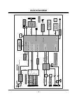
Page 27: ...lash Memory 16MByte HDMI DVI RS 232C SDRAM 256Mbit X tal 54MHz Reset IC D class AMP Sub Micom MTV416 Sub Micom MTV416 EEP ROM HDMI Component RGB PC Audio Tuner Comp_1 LR Comp_2 LR RGB Phone LR AUDIO ADC Audio R L I2S I2S Audio Input MST3361 R G B H V Sync DVI Input Digital Output SDRAM 256Mbit x2 DDS Data 24 Hsync Vsync DE Clk 2X1 S W 2X1 S W HDCP IIC TMDS DDS SPDIF Y C IF P N for DTV SIF for NTSC...

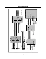
Page 28: ...LR Rear S YC LR Side S YC LR IN1 IN4 IN1 IN4 IN3 IN4 Comp_1 LR Comp_2 LR RGB Phone LR BCM3550 SD_Y SD_C ANT Cable TV IN CVBS from TUNER FMS6400 Y CVBS C OUT1 Y OUT1 C M_CVBS Y C M_CVBS C Y LPF for CVBS SD_CVBS TUNER IF_P IF_N IF_P from TUNER for DTV IF_N from TUNER for DTV ...

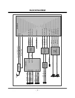
Page 29: ...002 Y G 3 YIN Pb B 5 PBIN Pr R 7 PBIN 1 EXT_SYNC 18 SYNC_IN 16 Comp_Y 15 Comp_Pb 14 Comp_Pr 44 GIN 43 SOGIN 41 BIN 46 RIN IC704 IC4009 RGB_G H Sync 7404 V Sync RGB_B RGB_R BCM3550 GPIO GPIO for sync selection HD DVI Data 24 H sync V sync DE Clock H V Sync Clock RGB_HS GPIO for sync selection RGB_HS RGB_VS RGB_HS RGB_VS GPIO GPIO for Component 1 GPIO GPIO for Component 2 GPIO for Component 2 GPIO f...

Page 30: ...C SCL1 EEPROM For EDID DDC SDA1 DDC SCL1 TMDS1 INPUT DDC1 INPUT TMDS2 RX0 TMDS2 RX1 TMDS2 RX2 TMDS2 RX3 DDC SDA2 DDC SCL2 EEPROM For EDID DDC SDA2 DDC SCL2 TMDS2 INPUT DDC2 INPUT HDCP SDA HDCP SCL EEPROM For HDCP NDA NCL INT DATA_OUT H V Sync DE Clock HDMI 1 HDMI 2 GPIO GPIO for Power detection 2 GPIO GPIO for Hot plug detection 2 GPIO for Power detection 2 GPIO for Hot plug detection 2 GPIO for P...

Page 31: ...3550 SIF I2S_LRCH_IN I2S_LRCK_IN I2S_SCK_IN I2S_LRCH_IN I2S_LRCK_IN SPDIF_IN_P SPDIF from MST3361 _R MNT_Out AUDIO DAC CS4344 I2S_SCK_OUT I2S_LRCH_OUT I2S_LRCK_OUT I2S_SCK_OUT I2S_LRCH_OUT I2S_LRCK_OUT _L MNT_Out Analog L_OUT Audio AMP TPA3100 SPDIF Out SPDIF_OUT_P AUD_LEFT_P AUD_LEFT_N AUD_RIGHT_N AUD_RIGHT_P SPK_L_P SPK_L_N SPK_R_N SPK_R_P Analog R_OUT MC3307 OP AMP IF_P from TUNER for DTV IF_N ...

Page 32: ... 32 EXPLODED VIEW 600 300 306 570 560 120 601 603 602 301 302 202 203 240 204 590 501 502 520 205 206 250 208 400 900 901 101 580 207 201 200 303 304 A2 ...

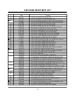
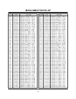
Page 33: ... ZB NON 50 PCM SECD 0 5t FOR SKD 501 AGU31681112 Plate Assembly PLATE TUNER BOT SMALL 42PC5_PACIFIC BCM D2A FOR CKD AGU31681102 Plate Assembly PLATE TUNER BOT SMALL PACIFIC2 BCM D2A 502 AGU31680918 Plate Assembly 42PC5D UC CKD AGU31680903 Plate Assembly PLATE TUNER COVER SMALL D2A BCM PACIFIC 520 EBR36496502 PCB Assembly Main PA73E 50PC5D UC KUSLLMR 50PC5D UC CKD Broadcom Model EBR36496501 PCB Ass...

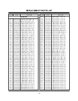
Page 34: ... NO DESCRIPTION IC1001 IC2002 IC2003 IC3001 IC4001 IC4003 IC4004 IC4006 IC4007 IC4008 IC4010 IC4011 IC4012 IC4013 IC4014 IC4016 IC4017 IC4018 IC5001 IC5002 IC5003 IC5004 IC6003 IC6004 IC6005 IC6006 IC7001 IC7002 IC7004 IC7005 IC7008 IC7010 IC7012 IC7013 IC7015 IC7016 IC7017 Q100 Q1001 Q1002 Q101 Q4001 Q4003 Q4004 0IPRP00702A 0IMMRIH038B 0IMMRIH038B EAN30267601 0IPRP00009A 0IPMGA0010A 0IKE702900G 0...

Page 35: ...nF 10 50V X 0603B103K500CT 10nF 10 50V X LOCA NO PART NO DESCRIPTION C1058 C1059 C1060 C1061 C1062 C1063 C1064 C1065 C2001 C2002 C2003 C2004 C2005 C2006 C2007 C2008 C2009 C2010 C2011 C2012 C2013 C2014 C2015 C2016 C2017 C2018 C2019 C2020 C2021 C2022 C2023 C2024 C2025 C2026 C2500 C2501 C2502 C2503 C2504 C2505 C2506 C2507 C2508 C2509 C2510 C2511 C2512 C2513 C2514 C2515 C2516 0CH2122K516 0CH2122K516 0...

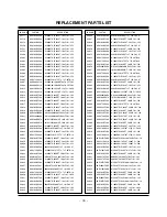
Page 36: ... 25V 0402B102K500CT 1nF 10 50V X7 C1005X7R104KET 100nF 10 16V C1005X7R1E103KT 10nF 10 25V LOCA NO PART NO DESCRIPTION C3046 C3047 C3048 C3049 C3050 C3051 C3052 C3053 C3054 C3055 C3056 C3057 C3058 C3059 C3060 C3061 C3062 C3063 C3064 C3065 C3066 C3067 C3068 C4001 C4002 C4003 C4004 C4005 C4006 C4007 C4008 C4010 C4011 C4012 C4014 C4015 C4016 C4019 C4020 C4021 C4022 C4023 C4024 C4025 C4026 C4028 C4030 ...

Page 37: ...R104KET 100nF 10 16V RC1A336M05005VR 33uF 20 10V RC1A336M05005VR 33uF 20 10V LOCA NO PART NO DESCRIPTION C4106 C4107 C4108 C4109 C4114 C4115 C4116 C4117 C4118 C4119 C4120 C4121 C4122 C4123 C4124 C4125 C4126 C4127 C4128 C4129 C4130 C4131 C4132 C4133 C4134 C4135 C4136 C4137 C4138 C4139 C4140 C4141 C4142 C4143 C4144 C4145 C4146 C5001 C5002 C5003 C5004 C5005 C5006 C5007 C5008 C5009 C5010 C5011 C5012 C...

Page 38: ...20 16V MVK4 0TP16VC10M 10uF 20 16V MVK4 0TP16VC10M 10uF 20 16V C1005X7R104KET 100nF 10 16V LOCA NO PART NO DESCRIPTION C5074 C5075 C5076 C5077 C5078 C5079 C5080 C5102 C5103 C5104 C5105 C5106 C5107 C5108 C5109 C6010 C6011 C6012 C6013 C6014 C6015 C6016 C6017 C6018 C6019 C6020 C6021 C6022 C6023 C6024 C6025 C6026 C6027 C6028 C6029 C6030 C6031 C6032 C6033 C6034 C6035 C7001 C7002 C7003 C7007 C7015 C7019...

Page 39: ...104KET 100nF 10 16V C1005X7R104KET 100nF 10 16V C1005X7R104KET 100nF 10 16V C1608X7R1E473KT 47nF 10 25V C1608X7R1E473KT 47nF 10 25V LOCA NO PART NO DESCRIPTION C7075 C7076 C7077 C7078 C7079 C7080 C7081 C7082 C7083 C7084 C7085 C7086 C7087 C7088 C7089 C7090 C7091 C7092 C7095 C7096 C7097 C7098 C7099 C7100 C7108 C7109 C7110 C7141 C7142 C7143 C7144 C7150 C7151 C7152 C7153 C7154 C7155 C7156 C7157 C7158 ...

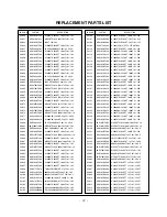
Page 40: ...K100 JK100 P7007 P7008 AR2001 AR2002 AR2003 AR2004 AR2005 AR2006 AR2007 AR2008 AR2009 AR2011 AR2012 AR2013 AR2014 AR2016 AR2017 AR2200 AR2201 AR2202 AR2203 AR2204 AR2205 AR2206 AR2207 AR2208 AR2209 AR2210 AR3021 AR6001 AR6002 AR6003 AR6004 AR6005 AR6006 AR6007 R100 R1006 R1008 R101 R101 R101 R1014 R1015 6612J10031A 6612F00024C 6612J10006K 6612J10033A EAG32151101 6612B00015C 6612B00015C 0RJ0222C692...

Page 41: ...71 470OHM 5 1 10W 16 MCR03EZPJ471 470OHM 5 1 10W 16 MCR03EZPJ471 470OHM 5 1 10W 16 LOCA NO PART NO DESCRIPTION R1068 R107 R1073 R1074 R1079 R108 R1080 R1081 R1083 R1084 R1085 R1086 R1087 R1088 R1129 R1131 R1132 R1133 R1134 R1135 R1136 R1137 R1139 R1140 R1141 R1142 R1144 R1145 R1157 R1158 R1159 R1160 R1161 R1162 R2003 R2013 R2015 R2016 R2017 R2026 R2027 R2102 R2103 R2104 R2105 R2106 R2107 R2108 R21...

Page 42: ...CR01MZPJ220 22OHM 5 1 16W 100 MCR01MZPJ220 22OHM 5 1 16W 100 MCR01MZPJ220 22OHM 5 1 16W 100 LOCA NO PART NO DESCRIPTION R3051 R3052 R3057 R3059 R3060 R3061 R3062 R3063 R3064 R3065 R3066 R3067 R3068 R3069 R3072 R3073 R3074 R3075 R3076 R3077 R3079 R3080 R3081 R3082 R3083 R3084 R3085 R3086 R3087 R3088 R3089 R3090 R3091 R3092 R3093 R3094 R3095 R3096 R3097 R3098 R3099 R3100 R3101 R3102 R3103 R3104 R310...

Page 43: ...CR03EZPJ473 47KOHM 5 1 10W 16 MCR01MZPJ220 22OHM 5 1 16W 100 MCR01MZPJ220 22OHM 5 1 16W 100 LOCA NO PART NO DESCRIPTION R4070 R4071 R4073 R4074 R4075 R4076 R4077 R4079 R4080 R4082 R4083 R4085 R4086 R4087 R4088 R4089 R4090 R4091 R4092 R4093 R4094 R4096 R4098 R4099 R4100 R4101 R4102 R4103 R4105 R4106 R4108 R4109 R4110 R4112 R4113 R4114 R4115 R4123 R4124 R4125 R4126 R4127 R4128 R4129 R4130 R4131 R413...

Page 44: ... 16W 1005 MCR03EZPJ104 100KOHM 5 1 10W 1 MCR03EZPJ222 2 2KOHM 5 1 10W 1 LOCA NO PART NO DESCRIPTION R5030 R5031 R5034 R5035 R5036 R5037 R5038 R5039 R5040 R5042 R5044 R5045 R5046 R5048 R5049 R5050 R5052 R5053 R5054 R5055 R5057 R5058 R5059 R5060 R5061 R5062 R5063 R5064 R5065 R5066 R5067 R5068 R5069 R5070 R5071 R5072 R5073 R5074 R5075 R5076 R5077 R5078 R5079 R5080 R5081 R5082 R5083 R5084 R5085 R5086 ...

Page 45: ...W 100 MCR01MZPJ220 22OHM 5 1 16W 100 MCR01MZPJ220 22OHM 5 1 16W 100 MCR01MZPJ220 22OHM 5 1 16W 100 LOCA NO PART NO DESCRIPTION R6036 R6037 R6038 R6042 R6043 R6048 R6049 R6050 R6051 R6052 R6053 R6054 R6057 R6058 R6059 R6060 R6063 R6064 R6065 R6066 R6082 R6083 R6085 R6088 R7004 R7005 R7006 R7007 R7008 R7009 R7010 R7011 R7012 R7013 R7014 R7015 R7016 R7018 R7019 R7021 R7022 R7029 R7030 R7035 R7036 R70...

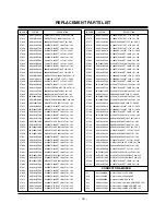
Page 46: ...J2R7 2 7OHM 5 1 10W 16 MCR03EZPJ2R7 2 7OHM 5 1 10W 16 MCR03EZPJ2R7 2 7OHM 5 1 10W 16 LOCA NO PART NO DESCRIPTION R7191 R7192 R7193 R7194 R7195 R7196 R7197 R7198 R7199 R7200 R7201 R7202 R7203 R7204 R7205 R7206 R7208 R7209 R7210 R7211 R7212 R7213 R7214 R7215 R7216 R7217 R7218 R7219 R7220 R7221 R7222 R7223 R7224 R7225 R7226 R7233 R7234 R7237 R7238 R7239 R7242 R7243 R7245 R7246 R7247 R7249 R7251 R7252...

Page 47: ...ead MLB 201209 0120P N2 120 Filter Bead MLB 201209 0120P N2 120 Filter Bead MLB 201209 0120P N2 120 Filter Bead HH 1M3216 501JT 500OHM Filter Bead HH 1M3216 501JT 500OHM Filter Bead HB 1S2012 080JT 8OHM 2X Filter Bead MLB 201209 0120P N2 120 Filter Bead MLB 201209 0120P N2 120 Filter Bead MLB 201209 0120P N2 120 LOCA NO PART NO DESCRIPTION L7019 L7021 L7022 L7023 L7024 L7025 L7026 L7027 L7037 L703...

Page 48: ...V C3061 0 1uF 16V D3 3V_BCM C3051 0 01uF 25V C3049 1000pF 50V C3045 0 01uF 25V D2 6V_BCM C3046 1000pF 50V C3048 0 01uF 25V 5 0V ZD3002 C3033 0 1uF 16V USB_DP R3112 1K R3109 1K USB_PWRFLT 3 3V C3030 0 01uF R3110 OPT ZD3004 USB_PWRON USB_DM R3111 2 7K ZD3001 ZD3003 C3034 10uF C3037 10uF R3117 OPT R3118 OPT 3 3V R3060 0 R3069 0 COMP1_SW COMP2_SW SW_COMP SW_COMP_PC R3124 4 7K R3123 4 7K 5 0V R3122 22 ...

Page 49: ...KP 16 RXB0N 17 RXB0P 18 GND_4 19 RXB1N 20 RXB1P 21 AVDD_DVI_3 22 RXB2N 23 RXB2P 24 GND_5 25 RXBCKN 26 RXBCKP 27 AVDD_DVI_4 28 REXT 29 GND_6 30 AVDD_PLL 31 DDCBSCL 32 DDCBSDA 33 AVDD_ADC_1 34 GND_7 35 VREFP 36 VREFN 37 HSYNC0 38 VSYNC0 39 AVDD_ADC_2 40 GND_8 41 BIN0P 42 BIN0N 43 SOGIN0 44 GIN0P 45 GIN0N 46 RIN0P 47 RIN0N 48 NC_1 49 NC_2 50 NC_3 51 NC_4 52 NC_5 53 NC_6 54 NC_7 55 NC_8 56 NC_9 57 AVD...

Page 50: ...nted in Korea P NO MFL36737202 CANADA LG Electronics Canada Inc 550 Matheson Boulevard East Mississauga Ontario L4Z 4G3 USA LG Electronics Alabama Inc P O Box 240007 201 James Record Road Bldg 3 Huntsville AL 35824 ...

Reviews: