- 10 -
LGE Internal Use Only
Copyright©2007 LG Electronics. Inc. All right reserved.
Only for training and service purposes
11. Adjustment of White Balance
11-1. Requirement
1) Before adjusting White-balance , the AV ADC should be
done.
2) If ADC status were “NG”, Need to ADC adjustment.
11-2. Required Equipment
1) Remote controller for adjustment.
2) Color Analyzer.( CA-1000,CA-100,100+,CA-210 or same
product ) : CH10(PDP)
* Please adjust CA-210, CA-100+ by CS-1000 before
measuring.
3) Auto W/B adjustment instrument.(only for Auto adjustment)
4) AV Pattern Generator.
W
Color temperature standards according to CSM and Module.
W
CS-1000/CA-100+/CA-210(CH10) White balance adjustment
coordinate and color temperature.
11-3. Connection Picture of the Measuring
Instrument(On Automatic control)
V
Inside PATTERN is used when W/B is controlled. Connect
to auto controller or push control R/C IN-START -> Enter
the mode of White-Balance, the pattern will come out.
V
Auto-control interface and directions
1. Adjust in the place where the influx of light like floodlight
around is blocked.(illumination is less than 10ux)
2. Measure and adjust after sticking the Color Analyzer(CA-
100+, CA210) to the side of the module.
3. Aging time
1) After aging start, keep the power on(no suspension of
poewr supply) and heat-run over 15minutes.
2) Keep white pattern using inside pattern.
V
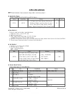
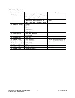
Auto adjustment Map(RS-232C)
- Baud : 115200bps, RS232 Host : PC, Echo : none
12. Adjustment of White Balance
(Manual white Balance)
V
One of R Gain/ G Gain/ B Gain should be kept on 80, and
others are controlled lowering from 80
(1) ‘power on’ of the control R/C, set heat run to white by
pressing and heat run over 15 minutes. (Set: RS-232 Host:
PC, Baud Rate: 115200bps, Download: Cortez)
(2) Zero Calibrate CA-100+, and stick the sensor to the center
of PDP module surface when you adjust.
(3) Double click In-start key on Controlling R/C and get in
‘white balance’.
(4) Set test-pattern on and display inside pattern. Control is
carried out on three color temperature, COOL, MEDIUM,
WARM. (Control is carried out three times.)
(5) When the R/G/B GAIN is 80 on OSD, it is the FULL
DYNAMIC Range of the Module. In order to control white
balance without the saturation of FULL DYNAMIC Range
and DATA, one of R Gain / G Gain / B Gain should be kept
on 80, and other two is controlled lowering from 80.
* Color Temperature: Cool, Medium, Warm
(1) When R GAIN is set to 80
- Control G GAIN and B GAIN by lowering from 80.
(2) When B GAIN is set to 80
- Control R GAIN and G GAIN by lowering from 80.
(3) When G GAIN is set to 80
- Control R GAIN and B GAIN by lowering from 80.
One of R Gain / G Gain / B Gain should be kept on 80, and
adjust other two lower than 80.
(When R/G/B GAIN are all 80, it is the FULL DYNAMIC
Range of Module)
(Fig. 6) Auto AV(CVBS) Color Balance Test Pattern
Full White Pattern
RS-232C Communication
CA-210
Color
ANALYZER
TYPE : CA-210
Color Coordinate
x
y
0.283±0.002
0.293±0.002
0.329±0.002
11000K
9300K
6500K
0.000
0.000
0.003
0.276±0.002
0.285±0.002
0.313±0.002
COOL
MEDIUM
WARM
Mode
Temp
uv
PLASMA
Remark
11000K
9300K
6500K
Cool
Normal
Warm
CSM
ADC adjust
Data Read
Default Write
Enter
Adjust Mode
ADC adjust
ADC Parameter
Digital Data
ADC Parameter
(Average)
Adjustment
Confirmation
Adjust ‘Mode In’
Adjust ‘Mode Off’
NO
Item
Remark
CMD1 CMD2 Data 0
A
A
A
A
A
A
A
D
D
D
D
D
D
D
0
0
0
0
9
0
0
1
2
3
4
9
0
9
Transfer 18Byte
(Input resolution Data)
To check ADC Adjusment
on Assembly line
When transger the ‘Mode
In’, Carry the command.
- Caution : Using ‘power on’ button’ of the control R/C, power in TV.
Type
Baud Rate
115200
Index
R Gain
G Gain
B Gain
R Offset
G Offset
B Offset
Data bit
8
Cmd1 Cmd2
j
a
j
b
j
c
j
d
j
e
j
f
Stop bit
1
Parity
NONE
PD73A
Protocol
Setting
Data
Min Value
00(00)
00(00)
00(00)
00(00)
00(00)
00(00)
Max Value
128(80)
128(80)
128(80)
128(80)
128(80)
128(80)


