background image

- 5 -

IC Remove/Replacement

Some chassis circuit boards have slotted holes (oblong) through
which the IC leads are inserted and then bent flat against the
circuit foil. When holes are the slotted type, the following technique
should be used to remove and replace the IC. When working with
boards using the familiar round hole, use the standard technique
as outlined in paragraphs 5 and 6 above.

Removal

1.  Desolder and straighten each IC lead in one operation by gently

prying up on the lead with the soldering iron tip as the solder
melts.

2.  Draw away the melted solder with an anti-static suction-type

solder removal device (or with solder braid) before removing the
IC.

Replacement

1.  Carefully insert the replacement IC in the circuit board.
2.  Carefully bend each IC lead against the circuit foil pad and

solder it.

3.  Clean the soldered areas with a small wire-bristle brush.

(It is not necessary to reapply acrylic coating to the areas).

"Small-Signal" Discrete Transistor
Removal/Replacement

1.  Remove the defective transistor by clipping its leads as close as

possible to the component body.

2.  Bend into a "U" shape the end of each of three leads remaining

on the circuit board.

3.  Bend into a "U" shape the replacement transistor leads.
4.  Connect the replacement transistor leads to the corresponding

leads extending from the circuit board and crimp the "U" with
long nose pliers to insure metal to metal contact then solder
each connection.

Power Output, Transistor Device
Removal/Replacement

1.  Heat and remove all solder from around the transistor leads.
2. Remove the heat sink mounting screw (if so equipped).
3.  Carefully remove the transistor from the heat sink of the circuit

board.

4.  Insert new transistor in the circuit board.
5. Solder each transistor lead, and clip off excess lead.
6.  Replace heat sink.

Diode Removal/Replacement

1.  Remove defective diode by clipping its leads as close as

possible to diode body.

2.  Bend the two remaining leads perpendicular y to the circuit

board.

3.  Observing diode polarity, wrap each lead of the new diode

around the corresponding lead on the circuit board.

4.  Securely crimp each connection and solder it.
5. Inspect (on the circuit board copper side) the solder joints of

the two "original" leads. If they are not shiny, reheat them and if
necessary, apply additional solder.

Fuse and Conventional Resistor
Removal/Replacement

1.  Clip each fuse or resistor lead at top of the circuit board hollow

stake.

2.  Securely crimp the leads of replacement component around

notch at stake top.

3.  Solder the connections.

CAUTION:

Maintain original spacing between the replaced

component and adjacent components and the circuit board to
prevent excessive component temperatures.

Circuit Board Foil Repair

Excessive heat applied to the copper foil of any printed circuit
board will weaken the adhesive that bonds the foil to the circuit
board causing the foil to separate from or "lift-off" the board. The
following guidelines and procedures should be followed whenever
this condition is encountered.

At IC Connections

To repair a defective copper pattern at IC connections use the
following procedure to install a jumper wire on the copper pattern
side of the circuit board. (Use this technique only on IC
connections).

1.  Carefully remove the damaged copper pattern with a sharp

knife. (Remove only as much copper as absolutely necessary).

2.  carefully scratch away the solder resist and acrylic coating (if

used) from the end of the remaining copper pattern.

3.  Bend a small "U" in one end of a small gauge jumper wire and

carefully crimp it around the IC pin. Solder the IC connection.

4.  Route the jumper wire along the path of the out-away copper

pattern and let it overlap the previously scraped end of the good
copper pattern. Solder the overlapped area and clip off any
excess jumper wire.

At Other Connections

Use the following technique to repair the defective copper pattern
at connections other than IC Pins. This technique involves the
installation of a jumper wire on the component side of the circuit
board.

1.  Remove the defective copper pattern with a sharp knife.

Remove at least 1/4 inch of copper, to ensure that a hazardous
condition will not exist if the jumper wire opens.

2.  Trace along the copper pattern from both sides of the pattern

break and locate the nearest component that is directly
connected to the affected copper pattern.

3.  Connect insulated 20-gauge jumper wire from the lead of the

nearest component on one side of the pattern break to the lead
of the nearest component on the other side.
Carefully crimp and solder the connections.

CAUTION:

Be sure the insulated jumper wire is dressed so the

it does not touch components or sharp edges.

Summary of Contents for 42LC46

Page 1: ...LCD TV SERVICE MANUAL CAUTION BEFORE SERVICING THE CHASSIS READ THE SAFETY PRECAUTIONS IN THIS MANUAL CHASSIS LD73A MODEL 42LC46 42LC46 ZC ...

Page 2: ... 2 CONTENTS CONTENTS 2 PRODUCT SAFETY 3 SPECIFICATION 6 ADJUSTMENT INSTRUCTION 14 TROUBLE SHOOTING 17 BLOCK DIAGRAM 25 EXPLODED VIEW 26 REPLACEMENT PARTS LIST 28 SVC SHEET ...

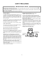
Page 3: ...Current Cold Check Antenna Cold Check With the instrument AC plug removed from AC source connect an electrical jumper across the two AC plug prongs Place the AC switch in the on position connect one lead of ohm meter to the AC plug prongs tied together and touch other ohm meter lead in turn to each exposed metallic parts such as antenna terminals phone jacks etc If the exposed metallic part has a ...

Page 4: ...vely obtain and wear a commercially available discharging wrist strap device which should be removed to prevent potential shock reasons prior to applying power to the unit under test 2 After removing an electrical assembly equipped with ES devices place the assembly on a conductive surface such as aluminum foil to prevent electrostatic charge buildup or exposure of the assembly 3 Use only a ground...

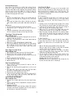
Page 5: ...not shiny reheat them and if necessary apply additional solder Fuse and Conventional Resistor Removal Replacement 1 Clip each fuse or resistor lead at top of the circuit board hollow stake 2 Securely crimp the leads of replacement component around notch at stake top 3 Solder the connections CAUTION Maintain original spacing between the replaced component and adjacent components and the circuit boa...

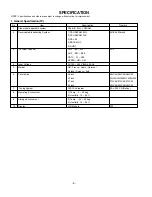
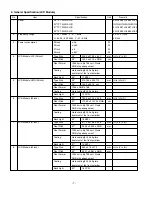
Page 6: ...AM L L 5 DVB T 3 RF Input Channel VHF E2 E12 PAL UHF E21 E69 CATV S1 S20 HYPER S21 S47 4 Input Voltage AC 100 240 V 50Hz 60Hz 5 Market UK France Spain German Finland Sweden Italy 6 Picture Size 26 inch 26LC45 26LC46 26LC55 32 inch 32LC45 32LC46 32LC55 32LC56 37 inch 37LC45 37LC46 37LC55 42 inch 42LC45 42LC46 42LC55 7 Tuning System FVS 100 program PAL 200 PR Option 8 Operating Environment 1 Temp 0 ...

Page 7: ... 712 mm H x V x D Pixel Pitch 26 140 5 x 421 5 um Pixel Format 1366 x RGB x 768 Coating Hard coating 3H Anti glare Back Light 26 12 CCFL 6 LCD Module 32inch Type Size 32 760 0 x 450 0 x 42 8 mm H x V x D Pixel Pitch 32 170 25 x 510 75 x RGB um Pixel Format 1366 horiz By 768 vert Pixels RGB strip arrangement Coating Hard coating 3H Anti glare treatment of the front polarizer Back Light 32 18 EEFL 7...

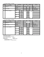
Page 8: ...mark 1 Viewing Angle CR 10 R L U D 178 178 2 Luminance Luminance cd m2 320 400 32 Variation 1 3 MAX MIN 3 Contrast Ratio CR 32 600 800 All white All black CRD With AI 32 1200 1600 All white All black 4 CIE Color Coordinates White Wx Typ 0 285 Typ 32 Wy 0 03 0 293 0 03 RED Xr 0 640 Yr 0 343 Green Xg 0 280 Yg 0 605 Blue Xb 0 145 Yb 0 065 No Item Specification Min Typ Max Remark 1 Viewing Angle CR 10...

Page 9: ...AX MIN 3 Contrast Ratio CR 42 600 800 All white All black CRD With AI 42 1200 1600 All white All black 4 CIE Color Coordinates White Wx Typ 0 281 Typ 42 Wy 0 03 0 293 0 03 RED Xr 0 630 Yr 0 343 Green Xg 0 275 Yg 0 607 Blue Xb 0 147 Yb 0 068 No Item Specification Min Typ Max Remark 1 Viewing Angle CR 10 R L U D 178 178 2 Luminance Luminance cd m2 360 400 37 Variation 1 3 MAX MIN 3 Contrast Ratio CR...

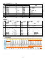
Page 10: ... 1080 33 75 60 00 HDTV 1080i 10 1920 x 1080 33 72 59 94 HDTV 1080i 5 RGB PC RGB PC INPUT Mode Table RGB PC EDID DATA No Resolution H freq kHz V freq Hz Pixel clock MHz Remark 1 720 x 400 31 468 70 08 28 321 2 640 x 480 31 469 59 94 25 17 VESA 37 684 75 00 31 50 3 800 x 600 37 879 60 31 40 00 VESA 46 875 75 00 49 50 4 832 x 624 49 725 74 55 57 283 5 1024 x 768 48 363 60 00 65 00 VESA XGA 56 470 70 ...

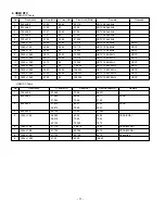
Page 11: ...74 176 HDTV 1080i 60Hz HDCP 11 1920 x 1080 33 75 60 74 250 HDTV 1080i 60Hz HDCP 12 1920 x 1080 27 24 74 250 HDTV 1080P 24Hz HDCP 13 1920 x 1080 56 25 50 00 148 500 HDTV 1080P 50Hz HDCP 14 1920 x 1080 67 43 59 94 148 352 HDTV 1080P 60Hz HDCP 15 1920 x 1080 67 50 60 148 500 HDTV 1080P 60Hz HDCP No Resolution H freq kHz V freq Hz Pixel clock MHz Remark 1 720 x 400 31 468 70 08 28 321 2 640 x 480 31 4...

Page 12: ... HDMI EDID DATA 1 HDMI 1 2 HDMI 2 12 ...

Page 13: ...g With BOX 16 6 Kg 4 37LC45 No Item Content Unit Remark 1 Product Widt W Length D Height H mm Dimension Before Packing 926 6 280 4 697 6 mm With Stant After Packing 999 264 874 mm Box Out Size 2 Product Only SET 20 Kg With BOX 25 Kg 5 37LC55 No Item Content Unit Remark 1 Product Widt W Length D Height H mm Dimension Before Packing 927 280 5 692 8 mm With Stant After Packing 1021 296 877 mm Box Out...

Page 14: ...ER RS 232 Host Gprobe Baud Rate 115200bps Download Cortez 3 Connect RS232 cable Use the general RS 232C Twisted Serial Cable 4 Operate LGIDS 5 Select Hurricane and ALL on Model dialog and check your connection in Communication dialog If your connection is NG then set your PORT COM1 2 3 correctly If your connection has completed you can see 6 Select proper CH_memory file nvm for each model at Chann...

Page 15: ...djustment is completed 4 3 Adjustment of Component Required Equipments Remote controller for adjustment MSPG 925FS Pattern Generator Which has 720p 50Hz YPbPr output Pattern shown in Fig 3 Model 215 Pattern 65 4 3 1 Method of Auto Component Color Balance 1 Input the Component 720p 50Hz 7 Color Bar MSPG 925FS model 215 pattern 65 signal into Component 2 Set the PSM to Dynamic mode in the Picture me...

Page 16: ...rs check the back light on 5 1 Manual white Balance One of R Gain G Gain B Gain should be kept on 80 and others are controlled lowering from 80 1 Press power on of the control R C set heat run to white by pressing G and heat run over 15 minutes Set RS 233 Host PC Baud Rate 115200bps Download Cortez 2 Zero Calibrate CA 210 and when controlling stick the sensor to the center of LCD module surface 3 ...

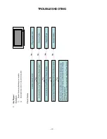
Page 17: ... 17 TROUBLESHOOTING ...

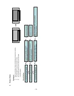
Page 18: ... 18 ...

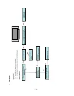
Page 19: ... 19 ...

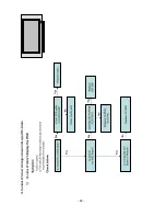
Page 20: ... 20 ...

Page 21: ... 21 ...

Page 22: ... 22 ...

Page 23: ... 23 ...

Page 24: ... 24 ...

Page 25: ...BLOCK DIAGRAM 25 ...

Page 26: ... 26 120 510 520 530 300 200 811 812 813 814 815 816 810 830 540 600 610 820 817 400 910 900 EXPLODED VIEW ...

Page 27: ...y Main MAIN1 T T LD73A 42LC7D ZN SEUVLJG Separation Tuner MAIN TOTAL 810 MGJ32902301 Plate PRESS EGI 1 2 FRAME SBHG A 42LY3 METAL BAR TOP FOR LPL MODULE 811 MGJ32902403 Plate PRESS EGI 1 6 FRAME SBHG A 42LC4 METAL BAR BOTTOM c Œ pem nut NO FOR LPL MODULE 812 MJH34248201 Supporter PRESS EGI 1 2 GUIDE EGI METAL BAR LEFT FOR V668 MODULE 813 MGJ32902704 Plate PRESS EGI 1 2 FRAME SBHG A 42LC4 METAL BAR...

Page 28: ... 100uF C528 0CE227WF6DC Capacitor AL Chip MVK8 0TP16VC220M 220uF C533 0CE107WF6DC Capacitor AL Chip MVK6 3TP16VC100M 100uF C534 0CE227WF6DC Capacitor AL Chip MVK8 0TP16VC220M 220uF C541 0CE107WF6DC Capacitor AL Chip MVK6 3TP16VC100M 100uF C543 0CE107WF6DC Capacitor AL Chip MVK6 3TP16VC100M 100uF C548 0CE107WF6DC Capacitor AL Chip MVK6 3TP16VC100M 100uF C549 0CE107WF6DC Capacitor AL Chip MVK6 3TP16...

Page 29: ...104CF56A Capacitor Ceramic Chip 0603B104K160CT 100nF 1 C122 0CK104CF56A Capacitor Ceramic Chip 0603B104K160CT 100nF 1 C123 0CK104CF56A Capacitor Ceramic Chip 0603B104K160CT 100nF 1 C1234 0CK102CK56A Capacitor Ceramic Chip 0603B102K500CT 1nF 10 C1235 0CK102CK56A Capacitor Ceramic Chip 0603B102K500CT 1nF 10 C1239 0CK104CK56A Capacitor Ceramic Chip 0603B104K500CT 100nF 1 C124 0CK104CF56A Capacitor Ce...

Page 30: ...147 0CK104CF56A Capacitor Ceramic Chip 0603B104K160CT 100nF 1 C148 0CK104CF56A Capacitor Ceramic Chip 0603B104K160CT 100nF 1 C149 0CK104CF56A Capacitor Ceramic Chip 0603B104K160CT 100nF 1 C150 0CK104CF56A Capacitor Ceramic Chip 0603B104K160CT 100nF 1 C151 0CK104CF56A Capacitor Ceramic Chip 0603B104K160CT 100nF 1 C152 0CK104CF56A Capacitor Ceramic Chip 0603B104K160CT 100nF 1 C153 0CK104CF56A Capaci...

Page 31: ...C413 0CK104CF56A Capacitor Ceramic Chip 0603B104K160CT 100nF 1 C415 0CK104CF56A Capacitor Ceramic Chip 0603B104K160CT 100nF 1 C429 0CK104CK56A Capacitor Ceramic Chip 0603B104K500CT 100nF 1 C430 0CK104CK56A Capacitor Ceramic Chip 0603B104K500CT 100nF 1 C516 0CK104CF56A Capacitor Ceramic Chip 0603B104K160CT 100nF 1 C518 0CK104CF56A Capacitor Ceramic Chip 0603B104K160CT 100nF 1 C520 0CK104CF56A Capac...

Page 32: ... C775 0CK104CK56A Capacitor Ceramic Chip 0603B104K500CT 100nF 1 C776 0CK104CK56A Capacitor Ceramic Chip 0603B104K500CT 100nF 1 C777 0CK104CK56A Capacitor Ceramic Chip 0603B104K500CT 100nF 1 C778 0CK104CK56A Capacitor Ceramic Chip 0603B104K500CT 100nF 1 C779 0CK104CK56A Capacitor Ceramic Chip 0603B104K500CT 100nF 1 C780 0CK104CK56A Capacitor Ceramic Chip 0603B104K500CT 100nF 1 C781 0CK104CK56A Capa...

Page 33: ...AH33945901 Diode TVS CDS3C30GTH 30V 50V 120 ZD100 EAH33945901 Diode TVS CDS3C30GTH 30V 50V 120 ZD101 EAH33946001 Diode TVS CDS3C05GTA 5 6V 6 4V 1 ZD102 EAH33946001 Diode TVS CDS3C05GTA 5 6V 6 4V 1 ZD103 EAH33945901 Diode TVS CDS3C30GTH 30V 50V 120 ZD104 EAH33945901 Diode TVS CDS3C30GTH 30V 50V 120 ZD1100 EAH33946001 Diode TVS CDS3C05GTA 5 6V 6 4V 1 ZD1101 EAH33946001 Diode TVS CDS3C05GTA 5 6V 6 4V...

Page 34: ... 6210TCE001G Filter Bead HH 1M3216 501JT 500OHM L1401 6210TCE001G Filter Bead HH 1M3216 501JT 500OHM L1403 6210TCE001G Filter Bead HH 1M3216 501JT 500OHM L1412 6210TCE001E Filter Bead HB 1M2012 800JT H 1mm L1413 6210TCE001E Filter Bead HB 1M2012 800JT H 1mm L400 6210TCE001G Filter Bead HH 1M3216 501JT 500OHM L606 6210TCE001G Filter Bead HH 1M3216 501JT 500OHM L607 6210TCE001G Filter Bead HH 1M3216...

Page 35: ...AR102 0RJ0472C687 Resistor Array RCA86TRJ47R0 47OHM 5 AR103 0RJ0472C687 Resistor Array RCA86TRJ47R0 47OHM 5 AR104 0RJ0472C687 Resistor Array RCA86TRJ47R0 47OHM 5 AR105 0RJ0472C687 Resistor Array RCA86TRJ47R0 47OHM 5 AR106 0RJ0472C687 Resistor Array RCA86TRJ47R0 47OHM 5 AR107 0RJ0472C687 Resistor Array RCA86TRJ47R0 47OHM 5 AR108 0RJ0472C687 Resistor Array RCA86TRJ47R0 47OHM 5 AR109 0RJ0472C687 Resi...

Page 36: ...1116 0RJ2203D677 Resistor Chip MCR03EZPJ224 220KOHM 5 R1117 0RJ0752D677 Resistor Chip MCR03EZPJ750 75OHM 5 R1118 0RJ1001D677 Resistor Chip MCR03EZPJ102 1KOHM 5 R1119 0RJ1001D677 Resistor Chip MCR03EZPJ102 1KOHM 5 R112 0RH0000D622 Resistor Chip MCR10EZHJ000 0OHM 5 1 R112 0RJ1002D677 Resistor Chip MCR03EZPJ103 10KOHM 5 R1120 0RJ4701D677 Resistor Chip MCR03EZPJ472 4 7KOHM 5 R1121 0RJ1001D677 Resistor...

Page 37: ...1 R1285 0RH0000D622 Resistor Chip MCR10EZHJ000 0OHM 5 1 R1286 0RH0000D622 Resistor Chip MCR10EZHJ000 0OHM 5 1 R1287 0RH0000D622 Resistor Chip MCR10EZHJ000 0OHM 5 1 R1288 0RH0000D622 Resistor Chip MCR10EZHJ000 0OHM 5 1 R1289 0RH0000D622 Resistor Chip MCR10EZHJ000 0OHM 5 1 R129 0RJ0472D677 Resistor Chip MCR03EZPJ470 47OHM 5 R1290 0RH0000D622 Resistor Chip MCR10EZHJ000 0OHM 5 1 R1291 0RH0000D622 Resi...

Page 38: ...474 470KOHM 5 R1454 0RJ4703D677 Resistor Chip MCR03EZPJ474 470KOHM 5 R1455 0RJ4701D677 Resistor Chip MCR03EZPJ472 4 7KOHM 5 R1456 0RJ1501D677 Resistor Chip MCR03EZPJ152 1 5KOHM 5 R146 0RJ2701D677 Resistor Chip MCR03EZPJ272 2 7KOHM 5 R1460 0RJ1000C678 Resistor Chip MCR01MZPJ101 100OHM 5 R1461 0RJ1000C678 Resistor Chip MCR01MZPJ101 100OHM 5 R1462 0RJ1000C678 Resistor Chip MCR01MZPJ101 100OHM 5 R1463...

Page 39: ...MCR01MZPJ470 47OHM 5 R183 0RJ3300D677 Resistor Chip MCR03EZPJ331 330OHM 5 R184 0RJ3300D677 Resistor Chip MCR03EZPJ331 330OHM 5 R185 0RJ0472C678 Resistor Chip MCR01MZPJ470 47OHM 5 R186 0RJ0472C678 Resistor Chip MCR01MZPJ470 47OHM 5 R187 0RJ0472C678 Resistor Chip MCR01MZPJ470 47OHM 5 R188 0RJ0472D677 Resistor Chip MCR03EZPJ470 47OHM 5 R189 0RJ0000G676 Resistor Chip MCR18EZHJ00 0OHM 5 1 R192 0RJ4701D...

Page 40: ...31KOHM R523 0RJ1001D677 Resistor Chip MCR03EZPJ102 1KOHM 5 R524 0RJ0000D677 Resistor Chip MCR03EZPJ000 0OHM 5 1 R526 0RJ2001D677 Resistor Chip MCR03EZPJ202 2KOHM 5 R527 0RJ2001D677 Resistor Chip MCR03EZPJ202 2KOHM 5 R528 0RJ0000D677 Resistor Chip MCR03EZPJ000 0OHM 5 1 R531 0RJ0000D677 Resistor Chip MCR03EZPJ000 0OHM 5 1 R534 0RJ1002D677 Resistor Chip MCR03EZPJ103 10KOHM 5 R536 0RJ1002D677 Resistor...

Page 41: ...ZPJ560 56OHM 5 R734 0RJ1000C678 Resistor Chip MCR01MZPJ101 100OHM 5 R735 0RJ1002D677 Resistor Chip MCR03EZPJ103 10KOHM 5 R737 0RJ4701D677 Resistor Chip MCR03EZPJ472 4 7KOHM 5 R739 0RJ1000C678 Resistor Chip MCR01MZPJ101 100OHM 5 R740 0RJ0222D677 Resistor Chip MCR03EZPJ220 22OHM 5 R741 0RJ1000C678 Resistor Chip MCR01MZPJ101 100OHM 5 R743 0RJ0000C678 Resistor Chip MCR01MZPJ000 0OHM 5 1 R744 0RJ0000C6...

Page 42: ...8 4320F16E33L 18 4 X700 6212AB2015J CrystalHC 49SM 19 66080HZ 19 J100 6612J10033A Jack Complex PMJ016 13 13P DIN RCA J1000 6612B00015C Jack DIN DC1R019WDH SOCKET 21P J1001 6612B00015C Jack DIN DC1R019WDH SOCKET 21P J1 6612BBBHN4D Jack Fiber Optic TOTX177 3P TX 2 54MM A J1101 6612F00099A Jack Phone PEJ024 01 1P 4P STRAIG J1203 6612J10031B Jack RCA PPJ209 01 14 0MM 1RX3C J600 6612J10023A Jack RCA KC...

Page 43: ......

Page 44: ......

Page 45: ......

Page 46: ......

Page 47: ...May 2007 Printed in Korea P NO MFL36695317 ...

Reviews: