background image

LED TV

LED TV

SERVICE MANUAL

SERVICE MANUAL

North/Latin 

North/Latin 

America 

America 

http://aic.lgservice.com

http://aic.lgservice.com

Europe/Africa 

http://eic.lgservice.com

Europe/Africa 

http://eic.lgservice.com

 Asia/Oceania 

 Asia/Oceania 

http://biz.lgservice.com

http://biz.lgservice.com

Internal Use Only

Internal Use Only

CHASSIS : LB45B

CHASSIS : LB45B

MODEL : 42LB550A

MODEL : 42LB550A

42LB550A-TA

42LB550A-TA

42LB552A

42LB552A

42LB552A-TB

42LB552A-TB

CAUTION

CAUTION

BEFORE SERVICING THE CHASSIS,

BEFORE SERVICING THE CHASSIS,

READ THE SAFETY PRECAUTIONS IN THIS MANUAL.

READ THE SAFETY PRECAUTIONS IN THIS MANUAL.

Summary of Contents for 42LB550A

Page 1: ...ce com Asia Oceania Asia Oceania http biz lgservice com http biz lgservice com Internal Use Only Internal Use Only CHASSIS LB45B CHASSIS LB45B MODEL 42LB550A MODEL 42LB550A 42LB550A TA 42LB550A TA 42LB552A 42LB552A 42LB552A TB 42LB552A TB CAUTION CAUTION BEFORE SERVICING THE CHASSIS BEFORE SERVICING THE CHASSIS READ THE SAFETY PRECAUTIONS IN THIS MANUAL READ THE SAFETY PRECAUTIONS IN THIS MANUAL ...

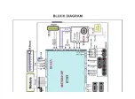
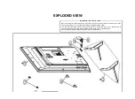
Page 2: ... CING PRECAUT PRECAUTIONS IONS 4 4 SPECIFIC SPECIFICA ATION TION 6 6 ADJUSTME ADJUSTMENT NT INSTRUCT INSTRUCTION ION 9 9 TROUBLE SHOOTING GUIDE TROUBLE SHOOTING GUIDE 13 13 BLOCK DIAGRAM BLOCK DIAGRAM 24 24 DISASSE DISASSEMBL MBLY Y WORKING WORKING GUIDE GUIDE 25 25 EXPLODE EXPLODED D VIEW VIEW 26 26 ...

Page 3: ...xide Metal Film Resistor When replacing a high wattage resistor Oxide Metal Film Resistor over 1 W keep the resistor 10 mm away from PCB over 1 W keep the resistor 10 mm away from PCB Keep wires away from high voltage or high temperature parts Keep wires away from high voltage or high temperature parts Before returning the receiver to the Before returning the receiver to the customer customer alwa...

Page 4: ...t required of contacts in not required 2 After removing an electrical assembly equipped with ES 2 After removing an electrical assembly equipped with ES devices place the assembly on a conductive surface such as devices place the assembly on a conductive surface such as aluminum foil to prevent electrostatic charge buildup or expo aluminum foil to prevent electrostatic charge buildup or expo sure ...

Page 5: ... connection 3 Solder the connections 3 Solder the connections CAUTION Maintain original spacing between the replaced CAUTION Maintain original spacing between the replaced component and adjacent components and the circuit board to component and adjacent components and the circuit board to prevent excessive component temperatures prevent excessive component temperatures Circuit Board Foil Repair Ci...

Page 6: ...by models 4 Specification and performance of each parts are followed each drawing and specification by part number in accordance with BOM 5 The receiver must be operated for about 5 minutes prior to the adjustment 3 Test method 1 Performance LGE TV test method followed 2 Demanded other specification Safety CE IEC specification EMC CE IEC 4 Model General Specification HDMI 1 4 with Deep Color is on...

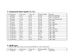
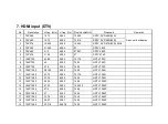
Page 7: ...20 44 96 59 94 74 176 HDTV 720P 8 1280 720 45 00 60 00 74 250 HDTV 720P 9 1280 720 37 50 50 00 74 25 HDTV 720P 50Hz 10 1920 1080 28 125 50 00 74 250 HDTV 1080I 50Hz 11 1920 1080 33 72 59 94 74 176 HDTV 1080I 12 1920 1080 33 75 60 00 74 25 HDTV 1080I 13 1920 1080 56 25 50 148 5 HDTV 1080P 14 1920 1080 67 432 59 94 148 350 HDTV 1080P 15 1920 1080 67 5 60 00 148 5 HDTV 1080P 6 HDMI input PC Spec out ...

Page 8: ...00 27 SDTV 576P 7 1280 720 44 96 59 94 74 176 HDTV 720P 8 1280 720 45 60 00 74 25 HDTV 720P 9 1280 720 37 5 50 00 74 25 HDTV 720P 10 1920 1080 28 125 50 00 74 25 HDTV 1080I 11 1920 1080 33 72 59 94 74 176 HDTV 1080I 12 1920 1080 33 75 60 00 74 25 HDTV 1080I 13 1920 1080 56 25 50 00 148 5 HDTV 1080P 14 1920 1080 67 43 59 94 148 350 HDTV 1080P 15 1920 1080 67 5 60 00 148 5 HDTV 1080P 16 1920 1080 27...

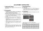
Page 9: ...20 minutes or longer especially where W B scale is strong Digital pattern 13ch and or Cross hatch pattern 09ch there can some afterimage in the black level area 4 EDID Download 4 1 Overview It is a VESA regulation A PC or a MNT will display an optimal resolution through information sharing without any necessity of user input It is a realization of Plug and Play 4 2 Equipment Since EDID data is emb...

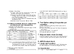
Page 10: ...ndicular of the module surface 80 100 3 Aging time 1 After Aging Start Keep the Power ON status during 5 Minutes 2 In case of LCD Back light on should be checked using no signal or Full white pattern 5 2 Equipment 1 Color Analyzer CA 210 NCG CH 9 WCG CH12 LED CH14 5 4 Adjustment Command Protocol 1 RS 232C Command used during auto adj 2 Adjustment Map 5 5 Adjustment method 5 5 1 Auto WB calibration...

Page 11: ...GD Module AUO INX COST SHARP BOE Module which cool spec is 13000K 6 Tool Option setting Inspection per countries 1 Press IN START key at Factory Service remote control 2 Select Tool Option 1 3 Punch in the number and press OK Each of models has their number 4 Correct Tool Option2 Tool Option5 5 Completed adjusting Tool option 7 Ship out mode check In stop After final inspection press In Stop key o...

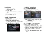
Page 12: ...message Copying files from memory 11 Optional adjustments 11 1 Manual ADC Calibration Enter EZ ADJUST mode by pressing ADJ key Enter Internal ADC calibration mode by pressing OK key at 3 ADC CALIBRATION Caution Using P ONLY button of the Factory SVC remote control when turns TV on If you can t success ADJUST ADC please confirm Support Int ADC at TOOL OPTION2 11 2 Manual White balance Adjustment 11...

Page 13: ......

Page 14: ...eristics These parts are identified by in the Schematic Diagram and EXPLODED VIEW It is essential that these special safety parts should be replaced with the same components as recommended in this manual to prevent X RADIATION Shock Fire or other Hazards Do not modify the original design without permission of manufacturer IMPORTANT SAFETY NOTICE ...

Page 15: ... E B C Q103 MMBT3904 NXP E B C Q104 MMBT3904 NXP READY E B C Q105 MMBT3904 NXP DEBUG E B C AV2_VIN R122 0 OPT R121 33 DEBUG C101 470pF 50V C102 470pF 50V C107 470pF 50V C108 470pF 50V JK101 PPJ239 06 6J 7J 4J 8K 5K 8L 5L 5M 4N 6N 7N 7D 5D 8E 5E 8F 6F 4F 5G 4H 6H 7H ZD110 20V ZD107 20V ZD109 20V ZD105 20V ZD104 20V ZD106 20V ZD108 SD05 READY ZD100 SD05 READY ZD102 SD05 READY ZD101 SD05 READY D102 D...

Page 16: ..._SCL 5V_USB HDMI2_D1 HDMI2_CK Q240 MMBT3904 NXP E B C R242 1K R241 10K HDMI2_D0 HDMI2_D2 HDMI2_D1 JK204 14 NC 13 CEC 5 DATA1_SHIELD 20 SHIELD 12 CLK 11 CLK_SHIELD 2 DATA2_SHIELD 19 HPD 18 5V_POWER 10 CLK 4 DATA1 1 DATA2 17 DDC CEC_GND 9 DATA0 8 DATA0_SHIELD 3 DATA2 16 SDA 7 DATA0 6 DATA1 15 SCL HDMI2_SDA R243 2 7K R244 2 7K HDMI2_D2 HDMI2_D0 ZD230 READY ZD231 READY ZD232 READY ZD233 READY R236 100...

Page 17: ... OPT 1uF C303 10V SW_RESET AUAMP_SDA 0 1uF C309 50V 0 1uF C318 50V 24V_AMP C327 390pF 50V I2S_WS R 30 6 1 00 C325 390pF 50V C305 33pF 50V R320 12 C301 0 1uF 16V R318 12 C311 22000pF 50V R311 100 READY C314 1uF 10V C308 22000pF 50V R319 12 24V_AMP I2S_SDO C328 390pF 50V R313 12 I2S_MCLK AUAMP_SCL C320 1000pF 50V R308 4 7K R309 4 7K 3 3V_M 0 1uF C322 16V R 30 1 1 00 R 30 2 1 00 R 30 3 1 00 L301 BLM1...

Page 18: ...OPT C426 100pF 50V 3 5V_ST C424 1000pF 50V LED C404 22uF 6 3V 100pF C406 50V TUNER_SCL TUNER_SDA L401 BLM18PG121SN1D R421 10K R422 10K R407 2 2K R408 2 2K R405 33 R406 33 C412 10uF 6 3V R413 10PAL R414 10 PAL R413 1 0 NTSC R414 1 0 NTSC ZD401 SD05 ZD402 SD05 R423 3 3K OPT TU401 TDJH G101D PA L 47 SHIELD 6 IF P 7 IF N 8 NC_2 9 NC_3 1 B1 3 3V 2 NC_1 3 IF_AGC 4 SC L 5 SD A A1 A1 B1 B1 P421 12507WR 10...

Page 19: ......

Page 20: ... 11 21 10 22 09 23 08 24 07 25 06 26 05 27 04 28 03 29 02 30 01 31 RXA2 RXA3 RXACK P602 FI RE51S HF J R1500 FHD 1 2 3 4 5 6 7 8 9 10 11 12 13 14 15 16 17 18 19 20 21 22 23 24 25 26 27 28 29 30 31 32 33 34 35 36 37 38 39 40 41 42 43 44 45 46 47 48 49 50 51 52 RXBCK RXB0 RXBCK RXA0 RXB3 RXB1 RXA1 RXB0 RXACK RXB2 PANEL_VCC RXB3 RXA2 RXB1 RXA1 RXA0 RXA3 RXB2 C602 1000pF 50V OPT C603 0 1uF 16V HD C601 ...

Page 21: ...EN 7 VCC 8 FB C775 0 1uF 16V C774 0 1uF R778 47K C771 1uF 25V R777 100K C770 10uF 16V 0 1uF C705 16V C772 0 1uF 16V L771 6 8uH NR8040T4R7N R770 43K 1 R772 8 2K 1 5V_USB C776 22uF 10V R748 33K R740 2 7K 1 R741 4 7K 1 IC711 AP1117E18G 13 2 OUT 3 IN 1 ADJ GND 3 5V_ST R716 10K R715 10K Q703 MMBT3904 NXP E B C R750 10K R E A D Y J P 7 0 8 J P 7 0 9 J P 7 1 0 J P 7 1 1 C753 4 7uF 10V ZD701 20V READY ZD7...

Page 22: ......

Page 23: ...e Inverter or module N Repair Power Board or parts End Always check record S W Version and White Balance value before replacing the Main Board Replace Main Board Re enter White Balance value Precaution Established date Standard Repair Process Revised date 1 14 LCD TV Error symptom A Video error No video Normal audio A1 First of all Check whether all of cables between board is inserted properly or ...

Page 24: ...wer Board 3 5V 12V 20V or 24V No Video No audio Check and replace MAIN B D Y Replace Power Board and repair parts N End Standard Repair Process A Video error No video No audio Established date Revised date 2 14 LCD TV Error symptom 2013 01 24 A4 ...

Page 25: ...problem or not By connecting RF Cable at other equipment DVD Player Set Top Box Different maker TV etc SVC Bulletin Replace Main B D Check Tuner soldering Normal Picture Y N Y Close Normal Picture Y Close Normal Picture Y Contact with signal distributor or broadcaster Cable or Air N N Normal Picture Y Close N Standard Repair Process Established date Revised date 3 14 LCD TV Error symptom 2013 01 2...

Page 26: ... N Y Close Check RF signal cable Check whether other equipments have problem or not By connecting RF Cable at other equipment Set Top Box Different maker TV etc Standard Repair Process Established date Revised date 4 14 LCD TV Error symptom Contact with signal distributor or broadcaster Close N Check Tuner soldering Replace Main B D 2013 01 24 A5 A6 ...

Page 27: ...V Component error Check external device and cable Y External device Cable normal HDMI error Check external device and cable Replace Main B D Replace Main B D N N A Video error Color error N Y End Replace module Request repair for external device cable Color error Check Test pattern Standard Repair Process Established date Revised date 5 14 LCD TV Error symptom 2013 01 24 Check and A7 A10 A8 A9 ...

Page 28: ...peration of External Input Component and HDMI by connecting Jig pattern Generator Set top Box etc N Y Replace Main B D Screen normal Check screen condition by input AV Component HDMI Request repair for external device Component error HDMI Connect other external device and cable Check normal operation of External Input Component and HDMI by connecting Jig pattern Generator Set top Box etc Replace M...

Page 29: ...rted properly Check Power LED Replace Power B D Measure voltage of each output of Power B D N Y Normal voltage Replace Main B D Y OK Replace Main B D N Y Normal Check ST BY 3 5V Replace Power B D N Y Normal voltage Replace Power B D Y Standard Repair Process Established date Revised date 7 14 LCD TV Error symptom Stand By Red Close 2013 01 24 A11 A12 A13 A4 ...

Page 30: ...d date Revised date 8 14 LCD TV Error symptom Standard Repair Process POWEROFF_REMOTEKEY Power off by REMOTE CONTROL POWEROFF_OFFTIMER Power off by OFF TIMER POWEROFF_SLEEPTIMER Power off by SLEEP TIMER POWEROFF_INSTOP Power off by INSTOP KEY POWEROFF_AUTOOFF Power off by AUTO OFF POWEROFF_ONTIMER Power off by ON TIMER POWEROFF_RS232C Power off by RS232C POWEROFF_SWDOWN Power off by S W Download P...

Page 31: ...of Power Board Normal voltage Y N Replace Power Board and repair parts Check Speaker disconnection N Y Replace Speaker Replace MAIN Board End C Audio error No audio Normal video Disconnection Established date Revised date 9 14 LCD TV Error symptom Standard Repair Process 2013 01 24 A15 A16 ...

Page 32: ... only for External Input Connect and check other external device N Y Normal audio Check and fix external device Replace Power B D N Y Normal voltage Check input signal RF External Input signal Signal normal When RF signal is not received Request repair to external cable ANT provider Y Check audio B Voltage 24V Replace Main B D In case of External Input signal error Check and fix external device Re...

Page 33: ... Operating When turn off light in room Check Replace Baterry of R C Check Repair Cable connection Connector solder Normal operating Check B 3 5V On Main B D Normal Voltage Close N N Check 3 5v on Power B D Replace Power B D or Replace Main B D Power B D don t have problem Check IR Output signal Normal Signal N Y Repair Replace IR B D N Replace Main B D Y Standard Repair Process Established date Re...

Page 34: ...ut and Component Recognition error Check and fix external device cable RGB HDMI DVI Optical Recognition error Replace Main B D Replace Main B D Fix in accordance with technical information D Function error External device recognition error Established date Revised date 12 14 LCD TV Error symptom Standard Repair Process 2013 02 02 ...

Page 35: ... then proceed as shown in the solution manual For models without any fix information provide the description OR Mechanical noise is a natural phenomenon and apply the 1st level description When the customer does not agree apply the process by stage Describe the basis of the description in Part related to nose in the Owner s Manual E Noise Circuit noise mechanical noise Established date Revised dat...

Page 36: ... Module damage Cabinet damage Replace cabinet Replace remote controller Remote controller damage Stand dent Replace stand F Exterior defect Exterior defect Established date Revised date 14 14 LCD TV Error symptom Standard Repair Process 2013 02 02 ...

Page 37: ... Video error_Color error LCD TV connection diagram A7 10 11 Check Link Cable LVDS reconnection condition A8 A9 12 Adjustment Test pattern ADJ Key A10 13 A Video error_Vertical Horizontal bar residual image light spot LCD TV connection diagram A8 14 Check Link Cable LVDS reconnection condition A8 A9 15 Adjustment Test pattern ADJ Key A10 16 Defected Type caused by T Con Inverter Module Exchange T C...

Page 38: ...ff when on off while viewing POWER OFF MODE checking method A14 28 C Audio error_No audio Normal video Checking method in menu when there is no audio A15 29 Voltage and speaker checking method when there is no audio A16 30 C Audio error_Wrecked audio discontinuation Voltage and speaker checking method in case of audio error A16 31 D Function error_ No response in remote controller key error Remote...

Page 39: ... Technical Manual Check Back Light On with naked eye A Video error_No video Normal audio ALL MODELS A1 Established date Revised date Error symptom Content LCD TV Power On disjoint back case check lighting from the module 2013 02 15 ...

Page 40: ...shed date Revised date Error symptom Content LCD TV Measure DC Voltage applying to Module from Power Board Output Voltage from Power Board supply to Module Check Pin contacting statement and connection statement ALL MODELS 2013 02 15 Output Voltage is depend on inch 32 inch 65 6 86 9V 39 inch 117 3 142 2V 42 inch 141 8 164 3V ...

Page 41: ...ished date Revised date Error symptom Content LCD TV Entry method 1 Press the ADJ button on the remote controller for adjustment 2 Enter into W B ADJUST 3 After recording the R G B GAIN Offset value of Color Temp Cool Medium Warm re enter the value after replacing the MAIN BOARD 4 Confirm W B ADJUST OK at In start menu 2013 02 15 ...

Page 42: ...epair Process Detail Technical Manual Power Board voltage measuring method A Video error_No video Audio A4 Established date Revised date Error symptom Content LCD TV Check the DC 24V 12V 3 5V Edge LED 2013 02 15 ...

Page 43: ...checking method A Video error_Video error video lag stop 1 Checking method for remote controller for adjustment Press the IN START with the remote controller for adjustment Version ALL MODELS A6 Established date Revised date Error symptom Content LCD TV 2013 02 15 ...

Page 44: ...TV connection diagram 1 A Video error _Vertical Horizontal bar residual image light spot As the part connecting to the external input check the screen condition by signal A7 Established date Revised date Error symptom Content LCD TV ALL MODELS 2013 02 15 ...

Page 45: ...VDS connection condition Standard Repair Process Detail Technical Manual Check and replace Link Cable LVDS and contact condition A Video error_Color error ALL MODELS A8 A9 Established date Revised date Error symptom Content LCD TV 2013 02 15 ...

Page 46: ..._Color error You can view 6 types of patterns with White and Full White using the ADJ Key Checking item 1 Defective pixel 2 Residual image 3 MODULE error ADD BAR SCAN BAR 4 Video error Classification of MODULE or Main B D A10 Established date Revised date Error symptom Content LCD TV 2013 02 15 ...

Page 47: ...CNT Broken T Con Defect CNT Broken Solder defect CNT Broken Solder defect CNT Broken Solder defect CNT Broken Solder defect CNT Broken Abnormal Power Section Solder defect Short Crack Abnormal Power Section Solder defect Short Crack Appendix Exchange T Con Board 1 ...

Page 48: ...normal Power Section Solder defect Short Crack Abnormal Power Section Solder defect Short Crack Fuse Open Abnormal power section Noise GRADATION GRADATION Abnormal Display Appendix Exchange T Con Board 2 ...

Page 49: ...Appendix Exchange PSU LED driver No Light Dim Light Dim Light Dim Light No picture Sound Ok ...

Page 50: ...Appendix Exchange the Module 1 Panel Mura Light leakage Press damage Crosstalk Crosstalk Press damage Panel Mura Light leakage Press damage Un repairable Cases In this case please exchange the module ...

Page 51: ...B IC Defect Vertical Line Source TAB IC Defect Vertical Block Source TAB IC Defect Horizontal Block Gate TAB IC Defect Horizontal line Gate TAB IC Defect Gate TAB IC Defect Horizontal Block Gate TAB IC Defect Appendix Exchange the Module 2 Un repairable Cases In this case please exchange the module ...

Page 52: ...Standard Repair Process Detail Technical Manual Check front display LED B Power error _No power A11 Established date Revised date Error symptom Content LCD TV ST BY condition Red 2013 02 15 ...

Page 53: ...epair Process Detail Technical Manual Check power input voltage and ST BY 3 5V B Power error _No power A12 Established date Revised date Error symptom Content LCD TV Check the DC 24V 12V 3 5V Edge LED 2013 02 15 ...

Page 54: ...rd Repair Process Detail Technical Manual Checking method when power is ON B Power error _No power A13 Established date Revised date Error symptom Content LCD TV Check the DC 24V 12V 3 5V Edge LED 2013 02 15 ...

Page 55: ...ment 2 Enter to ENGINEER OPTION 3 Enter and Check POWER OFF HISTORY Standard Repair Process Detail Technical Manual POWER OFF MODE checking method B Power error _Off when on off whiling viewing ALL MODELS A14 Established date Revised date Error symptom Content LCD TV 2013 02 15 ...

Page 56: ...e AUDIO function of the Menu 3 Check whether TV Speaker is on Standard Repair Process Detail Technical Manual Checking method in menu when there is no audio C Audio error_No audio Normal video ALL MODELS A15 Established date Revised date Error symptom Content LCD TV 2013 02 15 ...

Page 57: ...nnector Connect the tester RX1 to the speaker terminal and if you hear the Chik Chik sound when you touch the GND and output terminal the speaker is normal Standard Repair Process Detail Technical Manual Voltage and speaker checking method when there is no audio C Audio error_No audio Normal video ALL MODELS A16 Established date Revised date Error symptom Content LCD TV Check the DC 24V 12V 3 5V 2...

Page 58: ...ck the st by 3 5V on the terminal 4 Standard Repair Process Detail Technical Manual Remote controller operation checking method D Function error_ No response in remote controller key error ALL MODELS A17 Established date Revised date Error symptom Content LCD TV 2013 01 09 ...

Reviews: