background image

- 11 -

EDID DATA for RGB
EDID table =

5. MST9883-Set Adjustment

5-1. Synopsis

MST9883-Set adjustment to set the black level and the Gain
of optimum with an automatic movement from the analog =>
digital converter.

5-2. Test Equipment 

Service R/C, MSPG925FA Pattern Generator(720P The
Horizontal 100% Color Bar Pattern output will be possible and
the output level will accurately have to be adjusted to
0.7±0.1Vp-p)

5-3. Adjustment

(1) Select Component1 or Component2 as the input with

100% Horizontal Color Bar Pattern(HozTV31Bar) in 720p
Mode and select ‘Normal’ on screen.  

(2) After receiving signal for at least 1 second, press the ADJ

Key on the Service R/C to enter the ‘Ez - Adjust’ and select
the ‘2. MST9883-Set’.
Pressing the Enter Key to adjust with automatic movement.  

(3) When the adjustment is over, 'MST9883 Component

Success’ is displayed. If the adjustment has errors,
'MST9883 Configuration Error’ is displayed.

(4) After the Component MST9883 adjustment is over, convert

the RGB-DTV Mode and display Pattern. 
When the adjustment is over, 'MST9883 RGB_DTV
Success’ is displayed. If the adjustment has errors,
'MST9883 Configuration Error’ is displayed.

(5) Readjust after confirming the case Pattern or adjustment

condition where the adjustment had errors. 

(6) After adjustment is complete, exit the adjustment mode by

pressing the ADJ KEY.

6. Adjustment of White Balance

6-1. Required Equipment

(1) Color analyzer (CA-110, CA-210 or similar product)
(2) Automatic adjustor (with automatic adjustment hour

necessity and the RS-232C communication being possible)

(3)  Pattern Generator(MSPG-925FA): DVI Output

[ RS-232C Command

(Automatic Adjustment)

6-2. Adjustment of White Balance

Operate the Zero-calibration of the CA-210, then attach

sensor to module surface when you adjust.

Manual adjustment is also possible by the following sequence.  

(1) Enter ‘Ez - Adjust’ by pressing ADJ KEY on the Service

Remote Control.

(2) Select "8. WHITE PATTERN" using CH +/- Key and HEAT

RUN at least 30 minutes by pressing the ENTER Key.

(3) Receive the Window pattern signal from Digital Pattern

Generator. (AV Input: connect the ‘HDMI’)

(4) After attaching sensor to center of screen, select ‘5. White-

Balance’ of ‘Ez - Adjust’ by pressing the ADJ KEY on the
Service R/C. Then enter adjustment mode by pressing the
Right KEY (

) .

(5) Adjust the Hight Light using R Gain/G Gain(Cool).

Adjust the Hight Light using G Gain/B Gain(Medium).
Adjust the Hight Light using G Gain/B Gain(Warm).

(6) Adjust using /- KEY.

After adjustment is complete, exit the adjustment mode by
pressing the ADJ KEY.

High Level: 216gray

[Cool]
X; 0.274±0.002   Y; 0.275±0.002
Color temperature: 12000°K±1000°K

[Medium]
X; 0.287±0.002   Y; 0.289±0.002
Color temperature: 9300°K±1000°K

[Warm]
X; 0.315±0.002   Y; 0.316±0.002
Color temperature: 6500°K±1000°K

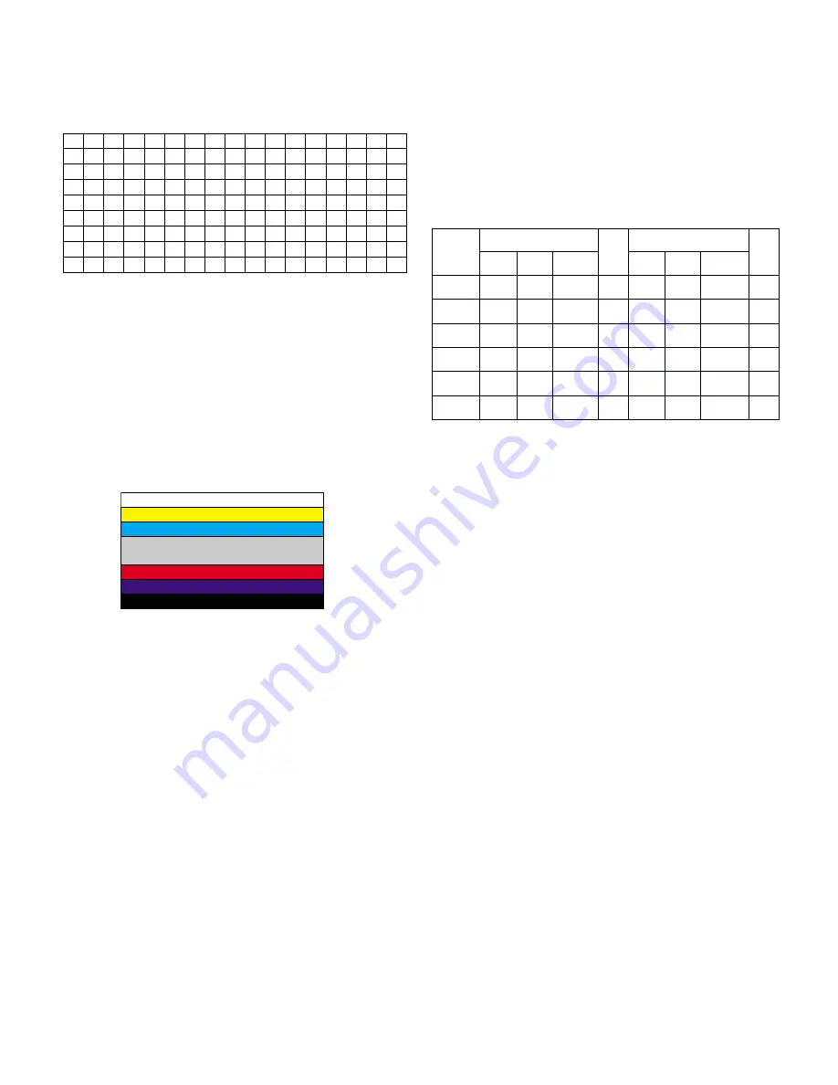
<Fig. 3>  Adjustment Pattern : 720P/60Hz HozTV31Bar Pattern

00 01 02 03 04 05 06 07 08 09 0A 0B 0C 0D 0E 0F

00 00 FF FF FF FF FF FF 00 1E 6D 5D 46 01 01 01 01
10 07 0F 01 03 68 46 28 96 0A D4 6C A3 57 49 9C 25
20 11 48 4B AF CE 00 31 4F 45 4F 61 4F 01 01 01 01
30 01 01 01 01 01 01 64 19 00 40 41 00 26 30 18 88
40 36 00 BC 88 21 00 00 18 00 00 00 FD 00 38 4B 1E
50 3D 08 00 0A 20 20 20 20 20 20 00 00 00 FC 00 33
60 32 4C 43 32 44 2D 55 44 0A 20 20 20 00 00 00 00
70 00 00 00 00 00 00 00 00 00 00 00 00 00 00 00 34

R Gain

G Gain

B Gain

R Cut

G Cut

B Cut

Jg

Jh

Ji

Cool

Ja

Jb

Jc

Med

RS-232C COMMAND

CENTER(DEFAULT)

Jd

Je

Jf

00

00

00

ff

ff

ff

7f

7f

7f

Warm

Min

Max

AE

BB

C0

70

67

64

Cool

B6

B2

9A

64

64

64

Med

C0

A5

5E

64

64

64

Warm

Summary of Contents for 32LC2DC

Page 1: ...ICE MANUAL CAUTION BEFORE SERVICING THE CHASSIS READ THE SAFETY PRECAUTIONS IN THIS MANUAL CHASSIS LA51D FACTORY NAME 32LC2DC MODEL 32LC2DC website http biz LGservice com e mail http www LGEservice com techsup html ...

Page 2: ... 2 CONTENTS CONTENTS 2 PRODUCT SAFETY 3 SPECIFICATION 6 ADJUSTMENT INSTRUCTION 10 TROUBLE SHOOTING 15 BLOCK DIAGRAM 22 WIRING DIAGRAM 23 EXPLODED VIEW 24 REPLACEMENT PARTS LIST 26 SVC SHEET ...

Page 3: ...Current Cold Check Antenna Cold Check With the instrument AC plug removed from AC source connect an electrical jumper across the two AC plug prongs Place the AC switch in the on position connect one lead of ohm meter to the AC plug prongs tied together and touch other ohm meter lead in turn to each exposed metallic parts such as antenna terminals phone jacks etc If the exposed metallic part has a ...

Page 4: ...vely obtain and wear a commercially available discharging wrist strap device which should be removed to prevent potential shock reasons prior to applying power to the unit under test 2 After removing an electrical assembly equipped with ES devices place the assembly on a conductive surface such as aluminum foil to prevent electrostatic charge buildup or exposure of the assembly 3 Use only a ground...

Page 5: ...not shiny reheat them and if necessary apply additional solder Fuse and Conventional Resistor Removal Replacement 1 Clip each fuse or resistor lead at top of the circuit board hollow stake 2 Securely crimp the leads of replacement component around notch at stake top 3 Solder the connections CAUTION Maintain original spacing between the replaced component and adjacent components and the circuit boa...

Page 6: ...1 This spec sheet is applied all of the 32 LCD TV with LA51D chassis 1 2 Not included spec and each product spec in this spec sheet apply correspondingly to the following each country standard and requirement of Buyer 2 Specification Each part is tested as below without special appointment 2 1 Temperature 20 5 C 2 2 Relative Humidity 65 10 2 3 Power Voltage Standard input voltage 110 240V 50 60Hz ...

Page 7: ...to LCD SPEC 4 Color coordinate RED X 0 640 0 03 Y 0 341 0 03 GREEN X 0 287 0 03 Y 0 610 0 03 BLUE X 0 146 0 03 Y 0 069 0 03 WHITE X 0 285 0 03 Y 0 293 0 03 5 Viewing angle 176 R L U D 6 Color Temperature Standard 8 300 9 300 10 300 Test Signal Cool 11 000 12 000 13 000 HDMI input With 16 gray Warm 5 500 6 500 7 500 pattern 6th bar from right 7 Color Distortion DG 8 Color Distortion DP deg 9 Color ...

Page 8: ...24 768 56 476 70 06 75 00 VESA XGA O 11 1024 768 60 023 75 02 78 75 VESA XGA O DTV 1 720 480 31 47 59 94 SDTV 480P 2 720 480 31 50 60 SDTV 480P 3 1280 720 45 00 60 00 HDTV 720P 4 1280 720 44 96 59 94 HDTV 720P 5 1920 1080 33 75 60 00 HDTV 1080I 6 1920 1080 33 72 59 94 HDTV 1080I 6 Component Video Input Y CB PB CR PR No Specification Proposed Resolution H freq kHz V freq Hz Pixel clock 1 720 480 15...

Page 9: ...68 48 363 60 00 65 00 VESA XGA O 9 1024 768 56 476 70 06 75 00 VESA XGA O 10 1024 768 60 023 75 02 78 75 O DTV 11 720 480 31 500 60 27 03 SDTV 480P 12 720 480 31 469 59 94 27 00 SDTV 480P 13 1280 720 45 00 60 00 HDTV 720P 14 1280 720 44 96 59 94 HDTV 720P 15 1920 1080 33 75 60 00 HDTV 1080I 16 1920 1080 33 72 59 94 HDTV 1080I 8 HDMI Input PC DTV 9 Mechanical specification No Item Content Remark 1 ...

Page 10: ...rammer click icon 5 End after confirming 4 EDID The Extended Display Identification Data DDC Display Data Channel download This is the function that enables Plug and Play 4 1 HDMI EDID Data Input 1 Required Test Equipment 1 Jig for adjusting PC DDC PC serial to D sub Connection equipment 2 S W for writing DDC EDID data write read 3 D Sub cable 4 Jig for HDMI Cable connection 2 Preparation for Adju...

Page 11: ...f White Balance Operate the Zero calibration of the CA 210 then attach sensor to module surface when you adjust Manual adjustment is also possible by the following sequence 1 Enter Ez Adjust by pressing ADJ KEY on the Service Remote Control 2 Select 8 WHITE PATTERN using CH Key and HEAT RUN at least 30 minutes by pressing the ENTER Key 3 Receive the Window pattern signal from Digital Pattern Gener...

Page 12: ... on the Service R C 3 Select 3 Video uPD Set and enter the adjustment mode by pressing the right key 4 When enter the adjustment mode displayed the TV 2CH Screen automatic at picture and appear as below figure 5 When the automatic adjustment is over RF Configuration Success is displayed If the adjustment has errors Video Configuration Error is displayed 6 After the RF signal automatic adjustment i...

Page 13: ...e 0 Treble 50 Bass 50 Front Surround Off TV Speaker On BBE Off 7 Timer Auto clock On Manual Clock Off Off Timer Off On Timer Off Sleep Timer Off Auto Off Off 8 Option Aspect Ratio 16 9 Cinema 3 2 mode Off Caption Off Caption Text CC1 Caption Option Off Language English 9 Lock Lock System Off Set password On Default 0000 Block channel None Movie Rating Off TV Rating Children None TV Rating General ...

Page 14: ...put To check the front AV To move channel up down or to select a function displayed on the screen To adjust the volume or accurately control a specific function To set a specific function or complete setting To move the channel down in the PIP screen To use as a red key in the teletext mode To move the channel in the PIP screen To use as a green key in the teletext mode To switch between the main ...

Page 15: ...circuit Doesn t the low pressure output come out Doesn t the St by 5V signal come out Yes Yes No 4 Check the 5V MNT signal circuit Doesn t the 5V Monitor signal come out Yes 7 Check the VSC Vs ON signal Doesn t the high tension output come out Doesn t the VSC signal Vs ON come out Yes Yes No 8 Check the Vs Va voltage output circuit Doesn t the Vs Va voltage output come out Yes No No 5 Check the VS...

Page 16: ... cord connected Plug in power cord Yes No Cable connecting the Line Filter and Power Board connected Connect Cable Yes No Is Fuse F101 on Power Board good Replace Fuse Yes No Is the Power Board connected to 7P of VSC Board Connect Cable Yes No When ST BY 5V does not operate replace Power Board ...

Page 17: ...ollow Check the LVDS cable Is the VSC Digital Board good Is the LVDS cable connected well Reset cable Yes No No Yes Operates the Thine IC IC100 Replace Thine IC IC100 No Is the T Con Board good Replace T Con B D No No Check IEP IC902 Replace IEP IC902 Yes No Check Scaler IC400 Replace VSC Digital B D Replace Scaler IC400 Yes Yes No Replace cable Yes ...

Page 18: ...Q good Is the Tuner Cable connected well Reset cable Yes No No Yes Is the Video Decoder IC302 UPD64011 good Replace Tuner No Are the Input voltage IIC Comm and CVBS outputs good Yes Are the Input voltage IIC Comm and HV sync good No Replace IC103 No Are the Input voltage IIC Comm and HV sync good No Replace IC302 No Is IC103 Switch CXA2069Q good Yes Is the Video Decoder IC302 UPD64011 good Is norm...

Page 19: ...oltage IIC Comm and HV sync good No Replace IC No Is normal the IC104 140538G Yes Is IC101 CXA2181Q good Are the Input voltage IIC Comm and HV sync good No Replace IC104 No Are the Input voltage IIC Comm and HV sync good No Replace IC101 No Yes Is normal the IC306 MST9883C Are the Input voltage IIC Comm and HV sync good No Replace IC306 No Yes Is IC400 Scaler good Are the Input voltage IIC Comm an...

Page 20: ... Input voltage IIC Comm and HV sync good No Replace IC306 No Is normal the M52758 Yes Is normal IC400 the Scaler Are the Input voltage IIC Comm and HV sync good No Replace IC306 No Is normal IC400 the Scaler Are the Input voltage IIC Comm and HV sync good No Replace IC400 No Are the Input voltage IIC Comm and HV sync good No Replace IC400 No Yes Is normal IC400 the Scaler Are the Input voltage IIC...

Page 21: ...nnected well Reset cable No No Reset cable No Replace IC1004 Replace IC1002 No No Replace IC1003 No Replace SPK cable Yes Yes Audio normal on RGB DVI Is the Flat cable connected well No No IC1004 MSP4440K good IC1002 NSP 2100A good Yes Replace VSC Analog B D IC1003 TAS5122 good Yes Yes Audio normal on RF AV Component No ...

Page 22: ...BLOCK DIAGRAM 22 ...

Page 23: ...027G 13P 6631900012J 10P 6631T25019T 12P 6631900037E 12P 6631900048A 4P 6631T20010C 10P 6631900010B 12P 6631V10003C 25P 6631V10004Z 31P 6631900092A 12P 6631T11020Z 30P 6631900019Q 4P 6631900018P 3P WIRING DIAGRAM ...

Page 24: ... 24 EXPLODED VIEW 010 020 060 050 070 080 090 100 030 130 040 041 042 110 120 ...

Page 25: ... 40 ...

Page 26: ... 41 ...

Page 27: ... 42 ...

Page 28: ... 43 ...

Page 29: ... 44 ...

Page 30: ... 45 ...

Page 31: ... 46 ...

Page 32: ... 47 ...

Page 33: ... 48 ...

Page 34: ... 49 ...

Page 35: ... 50 ...

Page 36: ... 51 ...

Page 37: ... 52 ...

Page 38: ... 53 ...

Page 39: ... 54 ...

Page 40: ... 55 ...

Page 41: ... 56 ...

Page 42: ...Aug 2006 Printed in Korea P NO 38289S0043 ...

Reviews: