background image

- 14 -

LGE Internal Use Only

Copyright  © 

  LG Electronics. Inc. All rights reserved.

Only for training and service purposes

4.5. DPM Operation check

■ Measurement Condition: 100~240V@ 50/60Hz

(1)  Set  Input  to  RGB-PC  and  connect  D-sub  cable  to  set  - 

RGB Mode. 

Set Input to HDMI(with Input Label set to PC) and connect 

HDMI cable to set - HDMI Mode

(2) Cut off H sync or V sync of signal.

(3) Check DPM operation refer to the below table.

■ HDMI DPM Operating condition

- Input Label: HDMI (PC&DVI Mode)

4.6. Model name & SW version & Adjust check

* Press the ‘Instart’ key of ADJ remote control.

4.6.1. Model Name& SW Version Check

(1) Check ‘Model Name’. 

(2) Check ‘S/W Version’ (Refer to the IC Ver. in the BOM)

4.6.2. Adjust Check

(1) Check ‘Country Group’

(2) Check ‘Area Option’

(3) Check ‘Tool Option’ (Refer to the BOM Comments) 

(4) Check ‘Adjust ADC[Comp&RGB]’ is OK.

(5) Check ‘EDID[RGB&HDMI]’ is OK.

*  After check all, Press the 'EXIT' key of ADJ remote control to 

go out SVC menu.

4.7.  Outgoing condition Configuration

*  After all function test., press IN-STOP key by SVC Remote 

control. And make Outgoing Condition.

Operating Condition

Sync(H/V) Video LED(SET) Wattage(W)

Power S/W On Sleep mode - 

RGB, HDMI

Off/Off

Off

Amber

1

MHL Cable

HDMI & HDMI to DVI Cable 

DPM

X

O

Summary of Contents for 29LN45

Page 1: ...D31S MODEL 29LN45 29LN45 Z CAUTION BEFORE SERVICING THE CHASSIS READ THE SAFETY PRECAUTIONS IN THIS MANUAL LED TV SERVICE MANUAL North Latin America http aic lgservice com Europe Africa http eic lgservice com Asia Oceania http biz lgservice com Internal Use Only ...

Page 2: ...s Inc All rights reserved Only for training and service purposes CONTENTS CONTENTS 2 SAFETY PRECAUTIONS 3 SERVICING PRECAUTIONS 4 SPECIFICATION 6 ADJUSTMENT INSTRUCTION 9 TROUBLE SHOOTING 15 BLOCK DIAGRAM 19 EXPLODED VIEW 20 SCHEMATIC CIRCUIT DIAGRAM ...

Page 3: ...inals etc to be sure the set is safe to operate without damage of electrical shock Leakage Current Cold Check Antenna Cold Check With the instrument AC plug removed from AC source connect an electrical jumper across the two AC plug prongs Place the AC switch in the on position connect one lead of ohm meter to the AC plug prongs tied together and touch other ohm meter lead in turn to each exposed m...

Page 4: ...ctrostatic charge on your body by touching a known earth ground Alter natively obtain and wear a commercially available discharg ing wrist strap device which should be removed to prevent potential shock reasons prior to applying power to the unit under test 2 After removing an electrical assembly equipped with ES devices place the assembly on a conductive surface such as aluminum foil to prevent e...

Page 5: ...he solder joints of the two original leads If they are not shiny reheat them and if necessary apply additional solder Fuse and Conventional Resistor Removal Replacement 1 Clip each fuse or resistor lead at top of the circuit board hollow stake 2 Securely crimp the leads of replacement component around notch at stake top 3 Solder the connections CAUTION Maintain original spacing between the replace...

Page 6: ...inland Netherlands Belgium Luxemburg Greece Denmark Czech Austria Hungary Swiss Croatia Turkey Norway Slovenia Poland Ukraine Portu gal Ireland Morocco Latvia Estonia Lithania Rumania Bulgaria Russia SlovakiaBosnia Serbia Albania Kazakhstan Belarus 4 Country Nordic option EU model only Denmark Finland Norway Sweden DTV MPEG2 4 DVB T2 8 countries UK Denmark Sweden Finland Norway Ireland Ukraine Kaz...

Page 7: ...s s to 7 2Msymbols s Modulation 16QAM 64 QAM 128 QAM and 256 QAM DVB S S2 symbolrate DVB S2 8PSK QPSK 2 45 Msymbol s DVB S QPSK 2 45 Msymbol s viterbi DVB S mode 1 2 2 3 3 4 5 6 7 8 DVB S2 mode 1 2 2 3 3 4 3 5 4 5 5 6 8 9 9 10 4 Scart Jack 1EA PAL SECAM Scart 1 Jack is Full scart and support RF OUT analog 5 Component Input 1EA Y Pb Pr 6 CVBS Input 1EA PAL SECAM NTSC 4 System Rear PAL SECAM NTSC PA...

Page 8: ... 59 810 83 500 9 1366 768 47 717 59 79 85 5 5 2 HDMI DTV No Specification Remark Resolution H freq kHz V freq Hz Pixel clock MHz 1 720 480 31 469 31 5000 59 940 60 000 27 000 27 030 SDTV 480P 2 720 576 31 250 50 000 27 864 SDTV 576P 3 1280 720 37 500 50 000 74 250 HDTV 720P 4 1280 720 44 960 45 000 59 940 60 000 74 170 74 250 HDTV 720P 5 1920 1080 33 720 33 750 59 940 60 000 74 170 74 250 HDTV 108...

Page 9: ...625I 50Hz 4 720 480 31 470 59 940 27 000 SDTV 480P 5 720 480 31 500 60 000 27 027 SDTV 480P 6 720 576 31 250 50 000 27 000 SDTV 576P 50Hz 7 1280 720 44 960 59 940 74 176 HDTV 720P 8 1280 720 45 000 60 000 74 250 HDTV 720P 9 1280 720 37 500 50 000 74 250 HDTV 720P 50Hz 10 1920 1080 33 720 59 940 74 176 HDTV 1080I 11 1920 1080 33 750 60 000 74 250 HDTV 1080I 12 1920 1080 28 125 50 000 74 250 HDTV 10...

Page 10: ...K message USB DOWNLOAD epk file download 1 Make New folder named LG_DTV and put ISP file epk in the folder 2 Put the USB Stick to the USB socket 3 Automatically detecting update file in USB Stick If your downloaded program version in USB Stick is Low it didn t work But your downloaded version is High USB data is automatically detecting 4 Show the message Copying files from memory 5 Updating is sta...

Page 11: ... push the INSTOP key after completion if the function inspection 3 3 CI key writing process Device CN 3 3 1 Communication Port Connection Connection PCBA USB Port USB to Serial Adapter UC 232A RS 232C cable PC RS 232C port Caution LD31Q LD31A chassis support only UC 232A driver only use this one 3 3 2 CI Key Download 1 Set CI Key path Directory at Start Mac CI Download Programme 2 Set COM 1 2 3 4 ...

Page 12: ...er D L 1 Press Power on key of service remote control 2 Connect RS232 Signal Cable to RS 232 Jack 3 Write Model Name Serial Number by use RS 232 4 Must check the serial number at the Diagnostics of SET UP menu Refer to below 4 2 2 Method notice 1 Model Name Serial Number D L is using of scan equipment 2 Setting of scan equipment operated by Manufacturing Technology Group 3 Serial number D L must b...

Page 13: ... 2 Adj Computer During auto adj RS 232C protocol is needed 3 Adjust Remote control RGB Gains are fixed data for each model Insert RS 232C Jack which is connected with PC for White Balance or equivalent device Total Assembly line should be check whether the color coordinate x y data refer to below table were meet or not Cool Panel Note x y coordinates are drifted about 0 007 after 30 mins heat run ...

Page 14: ...rsion Adjust check Press the Instart key of ADJ remote control 4 6 1 Model Name SW Version Check 1 Check Model Name 2 Check S W Version Refer to the IC Ver in the BOM 4 6 2 Adjust Check 1 Check Country Group 2 Check Area Option 3 Check Tool Option Refer to the BOM Comments 4 Check Adjust ADC Comp RGB is OK 5 Check EDID RGB HDMI is OK After check all Press the EXIT key of ADJ remote control to go o...

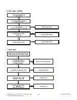
Page 15: ...N N Check IC802 output Voltage Level 12V Replace IC802 Recheck N Check IC809 Output Voltage Level 3 3V_ST Replace IC809 N Y Check IC800 Output Voltage Level 5V Replace IC800 N Y Y Y Y Check IC810 Output Voltage Level 2 5V Replace IC810 N Check IC806 Output Voltage Level 1 15V Replace IC806 N Y Check X201 Clock 24MHz Replace X201 N Replace IC100 Flash Memory Y Y Check IC807 Output Voltage Level 1 5...

Page 16: ...ce T con Board or module Check FFC Cable for damage or open conductors Replace Cable N Y Y Y Check LED Driver output LED Driver B d P1100 1 Check LED Driver IC1100 Replace LED Driver IC N Y 3 No Video Digital TV 1 29LN45 U 29LN45 R Check RF Cable Check Tuner TU2602 Data CLK SYN VAL Replace Tuner TU2602 Recheck Y N 1 Check Tuner TU2602 5 Power 3 3V 2 Check IC803 Output voltage 3 3V Replace IC803 Y ...

Page 17: ... IC803 Y N Check Tuner TU3702 I2C Signal SCL R3735 SDA R3736 Check IC101 Y N 1 Check Tuner TU3702 7 Power 1 8V 2 Check IC805 Output voltage 1 8V Replace IC805 Y N 3 29LN45 5 Check RF Cable Check Tuner TU2601 Data CLK SYN VAL Replace Tuner TU2601 Recheck Y N 1 Check Tuner TU2601 5 Power 3 3V 2 Check IC803 Output voltage 3 3V Replace IC803 Y N Check Tuner TU2601 I2C Signal SCL R2609 SDA R2610 Check ...

Page 18: ... Check Component Cable Wave form of C220 Wave form of C218 Wave form of C222 Wave form of Comp Y Wave form of Comp Pb Wave form of Comp Pr 5 No Video RGB Check input signal format Is it supported Check Hsync Vsync R266 R267 Replace R266 R267 Check signal RGB R228 R230 R232 C204 C206 C208 N Check JK400 Replace JK400 or Check Device Y N Y Replace R228 R230 R232 C204 C206 C208 N IC101 has problem Y C...

Page 19: ...connector Check I2C Signal JK501 15 16 Re download EDID data Y N Check HDCP Key IC101 Replace Scaler IC101 N 7 No Audio Make sure you can t hear any audio and Device support the audio signal normally Check Speaker and its wire connection P700 and the resistance Check Signal from IC700 L700 L701 L706 L709 Y Replace IC700 N Check R879 Voltage Level 3 3V Y Replace IC807 3 3V N Y Check Signal from IC1...

Page 20: ...3 SDRAM 1GB NAND Flash 1GB 74LCX244 Buffer IC501 CI_CLK CI_VIAL Error CI_SYNC CI_DATA 0 7 CI ADDR 0 7 PCM_DATA 0 7 PCM_A 0 7 CI_ADDR 0 14 REG CI_OE CI_IORD CI_IOWR CI WE PCM_A 0 14 FE_DE_SDA SCL SERIAL Flash CVBS Scart RGB TV L R Sound F_RB PF OE PF_CEO SPI_CK SPI_CI SPI_CS SPI_DO DDR2 Data 0 15 DDR2 Address 0 12 DDR2 Data 0 15 DDR2 Address 0 12 System EEPROM EEPROM SCL SDA Panel DMB LED Driver IC...

Page 21: ... and mechanical parts in this chassis have special safety related characteristics These parts are identified by in the Schematic Diagram and EXPLODED VIEW It is essential that these special safety parts should be replaced with the same components as recommended in this manual to prevent X RADIATION Shock Fire or other Hazards Do not modify the original design without permission of manufacturer IMP...

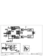
Page 22: ...ACRONIX 3 WP IO2 2 DO IO1 4 GND 1 CS 5 DI IO0 6 CLK 7 HOLD IO3 8 VCC IC100 1 MX25L8006EM2I 12G S_FLASH_MAIN_WINBOND 3 WP 2 SO SIO1 4 GND 1 CS 5 SI SIO0 6 SCLK 7 HOLD 8 VCC LNA_CTRL_1 LNA_CTRL_2 IC102 H27U1G8F2CTR BC NAND_1G_HYNIX_9103 DEV EAN35669103 26 NC_17 27 NC_18 28 NC_19 29 I O0 30 I O1 31 I O2 32 I O3 33 NC_20 34 NC_21 35 NC_22 36 VSS_2 37 VCC_2 38 NC_23 39 NC_24 40 NC_25 41 I O4 42 I O5 43...

Page 23: ...DC_2 H9 VDDC_3 K10 VDDC_4 K11 VDDC_5 L10 VDDC_6 M12 VDDC_7 M13 VDDC_8 N12 VDDC_9 P14 VDDC_10 P15 VDDC_11 R10 VDDC_12 R14 VDDC_13 R15 VDDC_14 T10 NC_2 P10 FB_CORE P19 AVDDL_MOD R16 NC_1 L11 DVDD_DDR M14 AVDD2P5_ADC_1 W9 AVDD2P5_ADC_2 W10 AVDD2P5_ADC_3 W11 AVDD2P5_ADC_4 W12 AVDD25_LAN Y17 AVDD_MOD_1 V18 AVDD_MOD_2 U19 NC_3 W14 NC_4 W15 AVDD_NODIE U7 AVDD_DVI_USB_1 L7 AVDD_DVI_USB_2 M7 AVDD3P3_MPLL P...

Page 24: ...5 CI_TS_DATA 3 PCM_REG SC1_R_IN PCM_IRQA SCART1_MUTE PCM_D 4 DTV MNT_VOUT CI_TS_DATA 7 PCM_A 9 PCM_RST PCM_D 0 PCM_D 1 PCM_D 2 CI_TS_DATA 4 PCM_CE PCM_A 13 PCM_D 5 SC1_G SCART1_Lout PCM_D 3 CI_TS_VAL CI_TS_DATA 2 PCM_WAIT PCM_A 10 CI_TS_DATA 0 CI_TS_SYNC CI_TS_DATA 1 SCART1_Rout SC1_SOG_IN PCM_CD PCM_A 12 PCM_A 14 PCM_A 8 PCM_IORD PCM_IOWR SC1_ID SC1_FB PCM_D 6 CI_CD2 PCM_WE SC1_B CI_DET SC1_L_IN ...

Page 25: ...2 ROUT1 13 RIN1 14 DOUT1 15 GND 16 VCC R459 0 NON_Hotel_Model RS232C Bypass P1104 12507WS 04L 1 2 3 4 5 DSUB_HSYNC 2 E18 VA427 20V OPT R451 0 JP413 R454 0 OPT PM_RXD PM_RXD 3 3V_Normal JP416 VA418 20V 5V_USB C420 47pF 50V R463 0 OPT IR_OUT R472 10K C426 0 1uF 16V Hotel_Model RS232C apply 3 3V_ST 3 3V_ST VA422 20V R443 75 C400 0 1uF VA428 20V OPT R441 75 C424 0 33uF 16V Hotel_Model RS232C apply R45...

Page 26: ...3D R500 47K D500 30V MBR230LSFT1G LN4500 HDMI_ARC R537 0 OPT LN4500MHL_OLD MHL_CD_SENSE IC500 BD82020FVJ LN4500 3 IN_2 2 IN_1 4 EN 1 GND 5 OC 6 OUT_1 7 OUT_2 8 OUT_3 R532 0 LN4500 R501 10K JK501 EAG61491201 14 13 5 D1_GND 20 SHIELD 12 11 2 D2_GND 19 18 10 CK 4 D1 1 D2 17 9 D0 8 D0_GND 3 D2 16 7 D0 6 D1 15 R538 10K OPT LN4500MHL_OLD D507 1 IP4283CZ10 TBA OPT ESD_HDMI_NXP 3 GND_1 2 TMDS_CH1 4 TMDS_C...

Page 27: ...3 100pF 50V OPT JP600 R617 3 3K KEY2 D603 30V OPT Q602 MMBT3904 NXP OPT IR_OUT E B C LED_AMBER R623 47K OPT IR_OUT LVA_0M LVA_1M JP609 R627 4 7K JP606 R619 10K OPT IR_OUT JP612 C606 10uF 25V LVA_3M P601 10031HR 30 1 2 3 4 5 6 7 8 9 10 11 12 13 14 15 16 17 18 19 20 21 22 23 24 25 26 27 28 29 30 31 LVA_2P KEY_SDA LVA_3P D601 30V R600 10K 3 3V_ST Q600 MMBT3904 NXP E B C 3 3V_ST R603 10K KEY1 LVA_2M Q...

Page 28: ...RCK L701 NRS6045T100MMGK Audio_Coil_ABCO 10 0uH R703 100 0 1uF C712 50V C4072 1uF 10V L709 1 NRS6045T100MMGK OPT Audio_Coil_TAIYO 10 0uH L706 1 NRS6045T100MMGK OPT Audio_Coil_TAIYO 10 0uH L700 1 NRS6045T100MMGK OPT Audio_Coil_TAIYO 10 0uH L701 1 NRS6045T100MMGK OPT Audio_Coil_TAIYO 10 0uH R4045 0 IC700 NTP7513 3 DGND_PLL 2 VDD_PLL 4 GND 1 AGND_PLL 6 DVDD 5 DGND 7 SDATA 8 WCK 9 BCK 10 SDA 11 SCL 12...

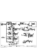
Page 29: ... 15V_VDDC C804 10uF 25V C805 10uF 10V R859 30K 1 BR FULL_NIM TEST POINT R844 10K 1 C892 1uF 10V Q805 PMV48XP G D S R806 10K OPT R849 0 5 C817 0 1uF 50V OPT C861 0 1uF 50V C816 0 1uF 50V L807 CPI2520NHL3R3ME 2520 3 3uH C863 0 1uF 50V C881 47pF 50V OPT C823 0 1uF 50V OPT R804 100K 1 OPT R800 100K 1 R867 4 7K 1 BR FULL_NIM R898 180K OPT C891 1uF 25V R847 0 R813 4 7K C899 0 1uF 50V OPT R888 47 C829 0 ...

Page 30: ... VDD_8 R1 VDD_9 R9 VDDQ_1 A1 VDDQ_2 A8 VDDQ_3 C1 VDDQ_4 C9 VDDQ_5 D2 VDDQ_6 E9 VDDQ_7 F1 VDDQ_8 H2 VDDQ_9 H9 NC_1 J1 NC_2 J9 NC_3 L1 NC_4 L9 NC_6 T7 VSS_1 A9 VSS_2 B3 VSS_3 E1 VSS_4 G8 VSS_5 J2 VSS_6 J8 VSS_7 M1 VSS_8 M9 VSS_9 P1 VSS_10 P9 VSS_11 T1 VSS_12 T9 VSSQ_1 B1 VSSQ_2 B9 VSSQ_3 D1 VSSQ_4 D8 VSSQ_5 E2 VSSQ_6 E8 VSSQ_7 F9 VSSQ_8 G1 VSSQ_9 G9 H5TQ1G63EFR PBC IC1201 1 DDR_1600_HYNIX_9003 DEV A...

Page 31: ...I_ADDR 9 CI_TS_CLK CI_TS_DATA 6 R1927 33 CI_ADDR 1 CI_WE CI_TS_DATA 7 CI_MDI 5 PCM_A 8 CI_ADDR 2 PCM_A 1 CI_MCLKI AR1901 33 PCM_A 6 R1904 10K AR1909 33 PCM_A 7 R1914 100 R1925 100 PCM_OE CI_IOWR CI_OE R1931 100 PCM_REG NAND_EN 3 3V_CI R1919 47 R1920 100 L1901 0 CI_IORD AR1903 33 R1916 0 OPT PCM_IOWR CI_MDI 2 CI_MDI 5 GND R1917 10K PCM_A 10 PCM_WE R1929 33 GND 5V_Normal AR1906 33 R1910 0 OPT AR1913...

Page 32: ...OPT BR FULL_NIM_D_DEMODE_0 R3801 0 OPT BR FULL_NIM_D_DEMODE_0 R3799 10K BR FULL_NIM R3798 1K BR FULL_NIM C3750 5pF 50V OPT C3751 5pF 50V OPT R3780 3 3 OPT R3781 3 3 OPT R3782 2K OPT R3756 0 OPT BR TU_NON_BUFFER_VIDEO R3751 220 BR TU_BUFFER_VIDEO R3750 1K OPT Q3703 MMBT3906 NXP BR TU_BUFFER_VIDEO E B C R3749 0 BR TU_BUFFER_VIDEO R3752 220 BR TU_BUFFER_VIDEO R3753 4 7K OPT BR TU_BUFFER_SIF R3774 470...

Page 33: ...0V OPT SCART_ADC_FILTER AUDIO D2807 20V OPT R2825 470K L2813 CM2012FR10KT OPT SCART_ADC_FILTER_L AUDIO SC1_B JP2809 R2842 1K C2834 47pF 50V OPT SCART_ADC_FILTER R2806 75 SCART JACK L2813 1 0 SCART_NON_ADC_FILTER AUDIO R2811 75 SCART JACK JK2800 PPJ234 05 5A GN O SPRING 6A GN E LUG 4A GN CONTACT 7B BL E LUG S 5B BL O SPRING 7C RD E LUG S 5C RD O SPRING_1 4C RD CONTACT_1 5D WH O SPRING 4E RD CONTACT...

Page 34: ...P 1 RC 5 FB 6 GND 7 ISNS 8 GDRV 9 BP 10 VDD 11 EP C2911 33uF 100V C1123 4700pF 50V R1121 100 C1124 33uF 100V R1124 47K 1 R1145 1M 1 8W 1 C2901 47uF 25V C1116 100pF 50V C2914 1uF 100V R2909 220K 1 16W R2903 10K 1 16W C2909 0 1uF 50V R1129 100K 1 L1101 33uH R2901 4 7K C1114 1000pF 50V 19V R2905 1K 1 16W 1 R1122 100K R1135 1 5K 1 C1127 0 1uF 250V D2901 100V BR210 R2907 680 1 8W 1 R2915 0 1 1W R1137 0...

Page 35: ......

Reviews: