background image

14

ASSEMBLING AND PREPARING

ENG

ENGLISH

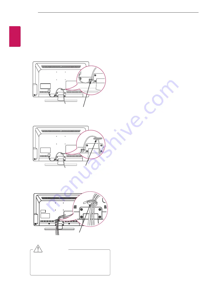
Tidying cables

Install the Power Cord Holder and Power Cord. 
It will help prevent the power cable from being 
removed by accident.

Only 32/37/42/47LT36**

Gather and bind the cables with the Cable 
Holder.

Only 22/26LT36**

Gather and bind the cables with the Cable 
Holder.

Cable Holder


CAUTION


y

Do not move the TV by holding the Cable 
Holder and Power Cord Holder, as the 
Cable holders may break, and injuries and 
damage to the TV may occur.

Cable Holder

Power Cord Holder

Summary of Contents for 22LT360C-ZA

Page 1: ...www lg com OWNER S MANUAL LED LCD TV Please read this manual carefully before operating your set and retain it for future reference LT36 ...

Page 2: ...nection 15 Antenna connection 16 HDMI connection 16 DVI to HDMI connection 17 RGB PC connection 17 RS 232C Setup 17 Component connection 18 Composite connection 18 Speaker output SETUP 18 USB connection 19 CI module connection 19 Euro Scart connection 20 REMOTE CONTROL 21 MAINTENANCE 21 Cleaning your TV 21 Screen frame cabinet and stand 21 Power cord 21 TROUBLESHOOTING 22 SPECIFICATIONS 24 IR CODE...

Page 3: ... the DivX VOD section in your device setup menu Go to vod divx com for more information on how to complete your registration DivX Certified to play DivX video up to HD 1080p including premium content DivX DivX Certified and associated logos are trademarks of Rovi Corporation or its subsidiaries and are used under license Covered by one or more of the following U S patents 7 295 673 7 460 668 7 515...

Page 4: ...3 Connect an external device to the TV set ASSEMBLING AND PREPARING Unpacking Check your product box for the following items If there are any missing accessories contact the local dealer where you purchased your product The illustrations in this manual may differ from the actual product and item CAUTION y y Do not use any unapproved items to ensure the safety and product life span y y Any damages ...

Page 5: ...unt Screw 1 EA Only 32 37 42 47LT36 See p 11 Power cord DC Adapter Only 22 26LT36 See p 15 Stand body Stand base Only 22LT36 See p 9 Stand body Stand base Only 26LT36 See p 9 Stand body Stand base Only 32 37 42 47LT36 See p 10 Protection cover Only 32 37 42 47LT36 See p 13 Isolator Depending on model See p 6 FREEZE RATIO L R SELECT ENTER BACK EXIT Q MENU INFO MENU CH VOL P A G E FAV 3D MUTE 1 2 3 ...

Page 6: ... after installation Before starting be sure that the TV antenna is connected ANTENNA CABLE IN Cable Antenna Wall Isolator 1 Connect to TV 2 Connect to Set Top box Connect one end of the isolator to cable antenna jack and the other to TV set or set top box Equipment connected to the protective earthing of the building installation through the mains connection or through other equipment with a conne...

Page 7: ...gh the saved programmes Adjusts the volume level Turns the power on or off Screen Power Indicator Can be adjusted using the Power Indicator in the OPTION menu Only 22 26LT36 Only 32 37 42 47LT36 COMPONENT IN USB IN IN 3 Speakers HDMI IN USB input COMPONENT IN PCMCIA Card Slot Remote control ...

Page 8: ...hen transporting a large TV there should be at least 2 people y y When transporting the TV by hand hold the TV as shown in the following illustration y y When transporting the TV do not expose the TV to jolts or excessive vibration y y When transporting the TV keep the TV upright never turn the TV on its side or tilt towards the left or right CAUTION y y Avoid touching the screen at all times as t...

Page 9: ...EPARING ENG ENGLISH Setting up the TV Image shown may differ from your TV Attaching the stand Only 22 26LT36 Front Stand Body Stand Base M4X20 Top View 1 2 3 M4 x 12 4 EA Only 22LT36 M4 x 12 4 EA M4 x 16 2 EA Only 26LT36 ...

Page 10: ...hes y y Make sure that the screws are inserted correctly and fastened securely If they are not fastened securely enough the TV may tilt forward after being installed Do not use too much force and over tighten the screws otherwise screw may be damaged and not tighten correctly NOTE y y Remove the stand before installing the TV on a wall mount by performing the stand attachment in reverse 4 EA M4 x ...

Page 11: ...V near or on sources of heat as this may result in fire or other damage WARNING y y To prevent TV from falling over the TV should be securely attached to the floor wall per installation instructions Tipping shaking or rocking the TV may cause injury 90 90 CAUTION y y When adjusting the angle of the product watch out for your fingers Personal injury may occur if hands or fingers are pinched If the ...

Page 12: ...pe Make sure to keep the rope horizontal with the flat surface CAUTION y y Make sure that children do not climb on or hang on the TV NOTE y y Use a platform or cabinet that is strong and large enough to support the TV securely y y Brackets bolts and ropes are not provided You can obtain additional accessories from your local dealer Mounting on a wall Attach an optional wall mount bracket at the re...

Page 13: ...ot provided when purchased with TV and wallmount LSW400B G Screw M6 x L45 can be used after separate purchase NOTE y y Use the screws that are listed on the VESA standard screw specifications y y The wall mount kit includes an installation manual and necessary parts y y The wall mount bracket is not provided You can obtain additional accessories from your local dealer y y The length of screws may ...

Page 14: ...oved by accident Only 32 37 42 47LT36 2 Gather and bind the cables with the Cable Holder Only 22 26LT36 1 Gather and bind the cables with the Cable Holder Cable Holder CAUTION y y Do not move the TV by holding the Cable Holder and Power Cord Holder as the Cable holders may break and injuries and damage to the TV may occur Cable Holder Power Cord Holder ...

Page 15: ...ng device to the TV use the cable supplied with the gaming device y y In PC mode there may be noise associated with the resolution vertical pattern contrast or brightness If noise is present change the PC output to another resolution change the refresh rate to another rate or adjust the brightness and contrast on the PICTURE menu until the picture is clear y y In PC mode some resolution settings m...

Page 16: ...PC to the TV Connect the PC and the TV with the HDMI cable as shown Choose any HDMI input port to connect It does not matter which port you use NOTE y y It is recommended to use the TV with the HDMI connection for the best image quality y y Use the latest High Speed HDMI Cable with CEC Customer Electronics Control function y y High Speed HDMI Cables are tested to carry an HD signal up to 1080p and...

Page 17: ... L 2 L MONO AUDIO VIDEO AUDIO IN RGB DVI COMPONENT R Not Provided PC GREEN GREEN GREEN BLUE BLUE BLUE WHITE RED RED RED RED WHITE RED VIDEO GREEN Not Provided AUDIO L R Not Provided Not Provided Blu Ray HD Cable Box DVD L MONO R AUDIO VIDEO AUDIO IN R L RGB DVI COMPONENT 2 R L COMPONENT IN USB IN IN 3 WHITE RS 232C Setup Connect the RS 232C serial port input jack to an external control device such...

Page 18: ...mits analog video and audio signals from an external device to the TV Connect the external device and the TV with th e composite cable as shown VIDEO MONO AUDIO L R L MONO R AUDIO VIDEO AUDIO IN R L RGB DVI COMPONENT 2 RED Not Provided VCR DVD Blu Ray HD Cable Box YELLOW WHITE RGB IN PC RS 232C IN CONTROL SERVICE ANTENNA IN 1 2 DC IN L MONO R AUDIO VIDEO AUDIO IN R L 2 R R L L RGB IN PC RS 232C IN...

Page 19: ...igital TV Digital TV Analogue TV AV Analogue TV Component RGB Analogue TV HDMI Analogue TV 1 TV Out Outputs Analogue TV or Digital TV signals NOTE y y Any Euro scart cable used must be signal shielded CI module connection View the encrypted pay services in digital TV mode This feature is not available in all countries NOTE y y Check if the CI module is inserted into the PCMCIA card slot in the rig...

Page 20: ... Number buttons Enters numbers LIST Accesses the saved programme list Q VIEW Returns to the previously viewed programme SETTINGS Accesses the main menus Q MENU Accesses the quick menus Navigation buttons up down left right Scrolls through menus or options OK Selects menus or options and confirms your input Back Returns to the previous level EXIT Clears on screen displays and return to TV viewing A...

Page 21: ...y Do not use any chemicals as this may damage the product y y Do not spray liquid onto the surface If water enters the TV it may result in fire electric shock or malfunction Power cord Remove the accumulated dust or dirt on the power cord regularly TROUBLESHOOTING Problem Solution Cannot control the TV with the remote control y y Check the remote control sensor on the product and try again y y Che...

Page 22: ...360C ZA Dimensions W x H x D With stand 766 0 mm x 536 0 mm x 231 9 mm 867 0 mm x 593 0 mm x 231 9 mm Without stand 766 0 mm x 476 0 mm x 68 5 mm 867 0 mm x 533 0 mm x 68 6mm Weight With stand 9 2 kg 11 2Kg Without stand 8 0 kg 10 0Kg Power requirement AC 100 240 V 50 60 Hz Power consumption 60W 90W MODELS 42LT36 47LT36 42LT360C ZA 47LT360C ZA Dimensions W x H x D With stand 992 0 mm x 667 0 mm x ...

Page 23: ...izontal Frequency kHz Vertical Frequency Hz 720x480 31 469 31 5 59 94 60 720x576 31 25 50 1280x720 37 5 44 96 45 50 59 94 60 1920x1080 33 72 33 75 28 125 26 97 27 33 716 33 75 56 25 67 43 67 5 59 94 60 50 23 97 24 29 976 30 00 50 59 94 60 Signal Component 480i 576i O 480p 576p O 720p 1080i O 1080p O 50 Hz 60 Hz only RGB PC HDMI DVI PC supported mode Resolution Horizontal Frequency kHz Vertical Fre...

Page 24: ...n AB GUIDE Remote control Button 45 Q MENU Remote control Button AA INFO Remote control Button 28 BACK Remote control Button 5B EXIT Remote control Button 44 OK Remote control Button 40 Remote control Button 41 v Remote control Button 07 Remote control Button 06 Remote control Button 72 RED Remote control Button 71 GREEN Remote control Button 63 YELLOW Remote control Button 61 BLUE Remote control ...

Page 25: ... No Connection 9 No Connection 12V available in some models RS 232C Configurations 3 Wire Configurations Not standard PC TV RXD 2 3 TXD TXD 3 2 RXD GND 5 5 GND DTR 4 6 DTR DSR 6 4 DSR RTS 7 7 RTS CTS 8 8 CTS D Sub 9 D Sub 9 7 Wire Configurations Standard RS 232C cable PC TV RXD 2 3 TXD TXD 3 2 RXD GND 5 5 GND DTR 4 6 DSR DSR 6 4 DTR RTS 7 8 CTS CTS 8 7 RTS D Sub 9 D Sub 9 Set ID Set ID number Real...

Page 26: ...01 Power k a 00 to 01 13 Treble k r 00 to 64 02 Aspect Ratio k c See p 28 14 Bass k s 00 to 64 03 Screen Mute k d See p 28 15 Balance k t 00 to 64 04 Volume Mute k e 00 to 01 16 Colour Temperature x u 00 to 64 05 Volume Control k f 00 to 64 17 Energy Saving j q 00 to 05 06 Contrast k g 00 to 64 18 Auto Con figuration j u 01 07 Brightness k h 00 to 64 19 Tune Com mand m a See p 30 08 Colour k i 00 ...

Page 27: ...x0 to 0x63 on transmission receiving protocol DATA To transmit command data Transmit FF data to read status of command Cr Carriage Return ASCII code 0x0D ASCII code space 0x20 OK Acknowledgement Command2 Set ID OK Data x The set transmits ACK acknowledgement based on this format when receiving normal data At this time if the data is data read mode it indicates present status data If the data is da...

Page 28: ...n off Data 00 Screen mute off Picture on Video mute off 01 Screen mute on Picture off 10 Video mute on In case of video mute on only TV will display On Screen Display OSD But in case of Screen mute on TV will not display OSD Transmission k d Set ID Data Cr Ack d Set ID OK NG Data x 05 Volume Control Command k f To adjust volume You can also adjust volume with the volume buttons on remote control D...

Page 29: ...screen sharpness You can also adjust sharpness in the PICTURE menu 10 Sharpness Command k k Data Min 00 to Max 64 Refer to Real data mapping See p 31 Transmission k k Set ID Data Cr Ack k Set ID OK NG Data x 15 Balance Command k t To adjust balance You can also adjust balance in the AUDIO menu Data Min 00 to Max 64 Refer to Real data mapping See p 31 Transmission k t Set ID Data Cr Ack t Set ID OK...

Page 30: ... reduce the power consumption of the TV You can also adjust Energy Saving in PICTURE menu Transmission j u Set ID Data Cr Ack u Set ID OK NG Data x Transmission j q Set ID Data Cr Ack q Set ID OK NG Data x 21 Key Command m c To send IR remote key code Data Key code See p 24 Transmission m c Set ID Data Cr Ack c Set ID OK NG Data x 20 Programme Add Skip Command m b To set skip status for the curren...

Page 31: ...5 23 Input select Command x b Main Picture Input To select input source for main picture Data Structure MSB LSB Transmission x b Set ID Data Cr External Input Input Number 0 0 0 0 0 0 0 0 Ack b Set ID OK NG Data x External Input Data 0 0 0 0 DTV 0 0 0 1 Analogue 0 0 1 0 AV 0 1 0 0 Component 0 1 1 0 RGB 0 1 1 1 HDMI 1 0 0 0 1 0 0 1 1 0 1 0 Input Number Data 0 0 0 0 Input1 0 0 0 1 Input2 0 0 1 0 Inp...

Page 32: ...The model and serial numbers of the TV is located on the back of the TV Record it below should you ever need service Model Serial ...

Reviews: