background image

- 10 -

(4) Dynamic Convergence (DYC) Adjustment

1) Vertical Line Adjustment : Adjust by moving DY right and

left

2) Horizontal Line Adjustment : Adjust by moving DY up

and down.

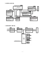
5-3. block diagram

Adjustment should be operated when using the CPT(without
ITC from CPT manufacturing place)

6. White Balance Adjustment

6-1. Necessary Instrument

1) Automatic White Balance Meter(Can generate Low/High

light Pattern)

2) White Balance meter(CRT Color Analyzer, CA-100) :1set
3) Factory Remote Control

6-2. Adjustment Preparation

: Prior to this adjustment, the Screen Voltage adjustment

should be finished.

6-3. Automatic adjustment

1) Adjust the using Automatic White Balance Meter.
2) Adjust in CPU OFF Mode by pressing IN-START, MUTE

key on the SVC Remote control. After finishing
adjustment, press the TV/AV key to exit.

(*In case there is excess RED color, adjust it using the
VOLUME - key of the remote control until the RED color
disappear.)

Color temperature : 12000°K
X Coordinate : 270±8
Y Coordinate : 283±8

6-4. Adjustment(Manual)

1) Adjust using white Balance meter and Factory Remote

controller.

2) Enter into adjustment mode by pressing the INSTART key
3) Use the CH

D

, CH

E

Key to choose adjustment item.

4) Use the VOL

F

, VOL

G

Key to change item data.

5) Adjustment Procedure

a. Make the picture luminance 45Ft-L by changing the

“CONTRAST” and “BRIGHTNESS”.

b. Adjust X data of High light with R-DRIVE(VP7) and Y

data with B-DRIVE(VP9) to have the color temperature
as shown below.

c. Make the picture luminance 4.5Ft-L by changing the

“CONTRAST” and “BRIGHTNESS”.

d. Adjust X data of low light with R-BIAS(VP4) and Y data

with B-BIAS(VP6) to have the color temperature as
shown below.

e. Repeat steps a~d until both low and high light have

same readings as shown below.

f.  Check the adjusted color coordinates with white balance

meter.

7. Focus Voltage Adjustment

This adjustment must be done after operating the TV set
receiver sufficiently.

7-1. Adjustment Preparation

1) Receive Digital pattern and Set the PSM condition to

“DYNAMIC”.

7-2. Adjustment

Adjust the upper Focus volume of FBT for the best focus of
horizontal line A, vertical B.

Assembling DY to

CPT

CPT Assembling

As preparatory operations before
assembling CPT, wind cotton Tape
for protecting to CPT NECK and DY,
CPT connection parts. At this
moment, end of tape should be over-
lapped and wound in direct route to
the NECK.

Let the screen Standard condition.
Operate Heat-Run at least 15
minutes. 

Torque is to be 9-11 kg f.cm when

fixing DY.

Fix the Magnet to the position as
shown picture below. Be careful not
to make CPT neck shadow while
adjusting DY.

HEAT RUN

Degaussing

STC Adjustment

PURITY Adjustment

DY Fixing

SCREEN Voltage adj.

W/B Fixing

FOCUS not yet ADJ.

STC not yet ADJ.

DYC not yet ADJ.

6pole   4        2 

15 ~ 20mm

Market           Color Temperature        X-AXIS         Y-AXIS

PAL model               14,000°K                 266±8          270±8

A

B

<Fig. 3>

Summary of Contents for 21FB5RB

Page 1: ...L CAUTION BEFORE SERVICING THE CHASSIS READ THE SAFETY PRECAUTIONS IN THIS MANUAL CHASSIS MC 059B MODEL 21FB5RB RG RGE RL MODEL 21FB5RB RG RGE RL TH website http biz LGservice com e mail http www LGEservice com techsup html ...

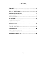
Page 2: ...TENTS 2 SAFETY PRECAUTIONS 3 DESCRIPTION OF CONTROLS 4 SPECIFICATIONS 7 ADJUSTMENT 9 PRINTED CIRCUIT BOARD 14 BLOCK DIAGRAM 15 TROUBLE SHOOTING 16 EXPLODED VIEW 20 EXPLODED VIEW PARTS LIST 21 REPLACEMENT PARTS LIST 22 ...

Page 3: ...perform an AC leakage current check on the exposed metallic parts of the cabinet such as antennas terminals etc to be sure the set is safe to operate without damage of electrical shock Leakage Current Cold Check Antenna Cold Check With the instrument AC plug removed from AC source connect an electrical jumper across the two AC plug prongs Place the AC switch in the on position connect one lead of ...

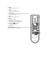
Page 4: ...on 4 EYE option switches the eye function on or off 5 D D E E Programme Up Down selects a programme or a menu item switches the set on from standby scans programmes automatically F F G G Volume Up Down adjusts the volume adjusts menu settings OK accepts your selection or displays the current mode 6 Q VIEW returns to the previously viewed programme 7 PSM Picture Status Memory recalls your preferred...

Page 5: ...he programme table 14 SLEEP sets the sleep timer 15 SSM Sound Status Memory option recalls your preferred sound setting 16 SURROUND º º option selects surround sound No function COLOURED BUTTONS These buttons are used for teletext only TELETEXT models or programme edit POWER MUTE 1 2 3 4 5 6 7 8 9 MENU INDEX TV AV 0 EYE Q VIEW LIST I II PR PR OK VOL VOL PSM SSM SLEEP PICTURE SOUND TURBO FAVOURITE ...

Page 6: ...t to these sockets 7 HEADPHONE SOCKET option Connect the headphone plug to this socket 8 EYE option adjusts picture according to the surrounding conditions 9 TV AV option selects TV or AV mode clears the menu from the screen switches the set on from standby 10 Function option selects volume EYE option picture items or brief auto programme while the menus not display 11 D D E E option adjusts the f...

Page 7: ...eceiver must be operated for about 20 minutes prior to the adjustment V Test Method 1 Performance LGE TV test method followed 2 Demanded other specification CCC Safety IEC60065 7 A General specification SPECIFICATIONS Note Specification and others are subject to change without notice for improvement Item Receiving System Available Channel Input Voltage Market Screen Size Aspect Ratio Display Metho...

Page 8: ...Monitor out 1 Front Power Vol F G PR E D MENU OK Turbo Picture Sound LG Code NEC System Storage Normal Turbo Storage System Channel Fine Search Name Copy Move Delete Skip 8 Channel Dynamic Standard Mild Game User Contrast Brightness Color Sharpness Tint NTSC M Only Flat Music Movie Speech User 0 100 100 400 1K 4K 10K Off On Pr 1 VOL 30 Off On On Off English Russia English Indonesia Thai Vietnam TV...

Page 9: ...s the ADJ key on LINE SVC remote control changes to screen adjustment mode 3 Adjust the Screen Vol of FBT to appear Horizontal Line and adjust the Screen Vol of FBT at disappear point Horizontal Line Press the Enter A key to exit SVC mode 5 Purity and Convergence Adjustment 5 1 Purity Adjustment 1 Adjustment Preparation 1 Receive Red Raster Pattern for purity adjustment 2 Demagnetize the CPT and C...

Page 10: ...and BRIGHTNESS b Adjust X data of High light with R DRIVE VP7 and Y data with B DRIVE VP9 to have the color temperature as shown below c Make the picture luminance 4 5Ft L by changing the CONTRAST and BRIGHTNESS d Adjust X data of low light with R BIAS VP4 and Y data with B BIAS VP6 to have the color temperature as shown below e Repeat steps a d until both low and high light have same readings as ...

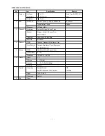
Page 11: ...E TABLE 3 OPTION 1 DVD TURBO ME V CURVE V MUTE EYE FLAT SND MUTE GAME OPTION2 TURBO ARC 200PR BLUEBACK TURBO AT HOTEL SHARP DVDN OPTION3 FM TRANS FM HIGH NTSC AV PSEU SYNC KI A2 SW LNA SWOOFER OPTION 4 SYSTEM SND MODE AV LOC KEY COLOR T PLL DIV MTS LEV OPTION 5 FM PRE NICAM PRE SCART PRE A2 FM TH FIRST TH ZWT TH INITIAL 0 0 0 0 0 1 1 0 0 0 0 1 1 0 0 1 0 0 1 1 1 0 0 0 4 1 2 1 1 31 22 6 13 0 5 15 2 ...

Page 12: ...at Bright ABL Threshold RGB Temp SW Coring Gain Select Pre shoot Adjustment Over shoot Adjustment Y Gamma start point Select DC Restoration Select Black Stretch Start Point Select Black Stretch Gain Select C Bypass C Kill On C Kill Off Color Killer Operational Point R B Gain Balance R B Angle B Y DC Level R Y DC Level Video Level OVER MOD SW OVER MOD LEVEL Tint Through Range 0 63 0 31 0 15 0 127 0...

Page 13: ...nput Auto Flesh WPL operating Point VM Gain Sensitivity of sync separation G Y Amplitude Color on off on Half tone Mode Overmodulation circuit Type APC Offset current IF video level offset 5 74MHz FM Det IF VCO freerun frequency Equalizer Bell filter Equalizer circuit Bell filter adjust SECAM Killer circuit disable SECAM Killer circuit enable OSD Contrast OSD Position Range 0 3 0 3 0 3 0 3 0 3 0 3...

Page 14: ... 14 PRINTED CIRCUIT BOARD MAIN ...

Page 15: ... 15 BLOCK DIAGRAM HIC291 ...

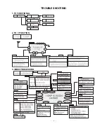
Page 16: ... 16 Maneuver defectiveness Maneuver defectiveness In case of influx NOISE R C is not operate Maneuver defectiveness 1 TV FUNCTIONAL 2 TU IF SECTION 3 VIDEO PROCESSING TROUBLE SHOOTING ...

Page 17: ... 17 4 SMPS PRIMARY SECTION 5 SMPS SECONDARY SECTION ...

Page 18: ... 18 6 VERTICAL SECTION 7 HORIZONTAL SECTION ...

Page 19: ...8 SOUND PROCESSING SECTION 19 9 CPT DRIVE SECTION ...

Page 20: ... 20 EXPLODED VIEW 913 170 150 112 330 320 120 300 121 310 520 P801 400 943 700 ...

Page 21: ...330 5020V00737A Button MOLD ABS RT 21FB50 ABS LGESY LOCAL 5020V00748D BUTTON POWER RT 21FB55V ABS HF 380 1KEY 84B MT LOCAL 5020V00858A BUTTON 21FB50 ABS PAKISTAN 400 3809V00323T Cover Assembly RT 21FB55VE 1PHONE 8G068 407AF SY C SKD 3809V00333M BACK COVER ASSEMBLY 21FB5RL TH DVD 1PHONE MC059B 3809V00333P BACK COVER ASSEMBLY 21FB5RB TH 1PHONE SY LGETH MONO MC059B 3809V00409C BACK COVER ASSEMBLY RT ...

Page 22: ...000PF D 25V 80 20 F Y5V TA52 100UF STD 10V M FL TP5 100UF STD 10V M FL TP5 10UF STD 16V M FL TP5 10UF STD 16V M FL TP5 220UF STD 10V M FL TP5 LOCA NO PART NO DESCRIPTION IC02 IC301 IC501 IC601 IC661 IC751 IC801 IC802 IC803 IC804 IC805 Q10 Q101 Q102 Q111 Q16 Q241 Q301 Q401 Q402 Q403 Q502 Q601 Q671 Q672 Q801 Q813 Q901 Q902 Q903 D111 D301 D302 D303 D403 D405 D501 D502 D505 D601 D602 D603 D604 0IMMR00...

Page 23: ...N C534 C535 C536 C537 C539 C540 C542 C544 C550 C56 C602 C603 C604 C605 C606 C607 C608 C609 C610 C611 C612 C613 C614 C653 C654 C655 C656 C657 C658 C659 C660 C662 C663 C664 C665 C667 C668 C670 C671 C673 C675 C676 C678 C680 C681 C682 C685 C687 C688 C691 C692 C693 0CN1030F679 0CN1030F679 0CE105DK618 0CN1010K519 0CN1010K519 0CE475DR618 0CQ1831N509 0CN2230H949 0CX4700K409 0CN4710K519 0CE337DH618 0CE475D...

Page 24: ... 4 INDUCTOR AXIAL LEAD 10UH K 2 3 3 4 TP INDUCTOR AXIAL LEAD 10UH K 2 3 3 4 TP INDUCTOR AXIAL LEAD 10UH K 2 3 3 4 TP LOCA NO PART NO DESCRIPTION L802 T403 T803 C1 C2 C3 C4 C5 P101 P601 P602 P801A P801B P802A P802B P901 C221 C222 C233 C234 FR301 FR401 FR403 FR501 FR825 J511 L212 R1 R101 R102 R103 R104 R105 R108 R109 R11 R110 R111 R112 R113 R121 R132 R150 R152 R153 R154 R16 R17 150 C02F 151 C02B 617...

Page 25: ... OHM 1 6 W 5 TA52 LOCA NO PART NO DESCRIPTION R509 R510 R512 R513 R514 R515 R516 R519 R521 R522 R523 R524 R525 R526 R527 R529 R530 R531 R532 R534 R536 R537 R547 R550 R552 R553 R554 R555 R556 R561 R562 R563 R564 R565 R566 R58 R601 R602 R603 R604 R605 R607 R609 R610 R611 R612 R613 R615 R616 R617 R618 R619 0RD3901F609 0RD3901F609 0RN4701F409 0RD1200F609 0RD1000F609 0RD0102F609 0RD1000F609 0RD1202F609...

Page 26: ...6 W 5 TA52 1 8K OHM 1 6 W 5 00 TA52 18K OHM 2 W 5 00 TA62 430 OHM 1 6 W 5 00 TA52 100 OHM 1 6 W 5 TA52 18K OHM 2 W 5 00 TA62 1 5K OHM 1 2 W 7 0 5 00 TA52 1 5K OHM 1 2 W 7 0 5 00 TA52 1 5K OHM 1 2 W 7 0 5 00 TA52 100 OHM 1 6 W 5 TA52 430 OHM 1 6 W 5 00 TA52 18K OHM 2 W 5 00 TA62 1M OHM 1 6 W 5 TA52 LOCA NO PART NO DESCRIPTION SW11 SW12 SW13 SW14 SW15 SW16 SW801 FB801 L804 T802 X1 X501 X661 Z111 Z60...

Page 27: ...P NO 3854VA0196B S1 2005 8 16 ...

Page 28: ...SVC SHEET 3854V A0196B S ...

Page 29: ...Mar 2006 Printed in Korea P NO 3828VD0235L ...

Reviews: