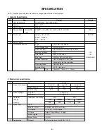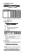
5.2. EEPROM DATA READ
(1) Signal Table
(2) Command Set
Purpose : To read the appointment Address of E2PROM by
128(80h)-byte
5.3. E
2
PROM Data Write
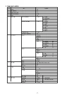
(1) Signal Table
LEN
: 84h+Bytes
CMD
: 8Eh
ADH
: E
2
PROM Slave Address(A0,A2,A4,A6,A8),
Not 00h(Reserved by BufferToEEPROM)
ADL
: E2PROM Sub Address(00~FF)
Data
: Write data
(2) Command Set
<Purpose>
1) EDID write : 16-byte by 16-byte, 8 order (128-byte) write
(TO “00 – 7F” of “EEPROM Page A4”)
2) FOS Default write : 16-mode data (HFh, HFl, VF, STD,
HP, VP, Clk, ClkPh, PhFine) write
3) Random Data write : write the appointment Address of
E2PROM
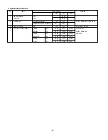
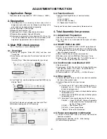
5.4. VRAM Read
1) Send CMD(70h) to read Video RAM value from MICOM
And save its value to 128-Bytes Buffer(Common Buffer for
the use of EDID).
2) Delay 500ms(Time to wait and read vZideo RAM from
MICOM)
3) Be transmitted the contents of MICOM’s 128-bytes Buffer to
PC.(128th Data is the CheckSum of 127-bytes data : That’s
OK if the value of adding 128-bytes Data is Zero)
- 11 -
ST OP
A
A
A
A
A
50
6E
03
CMD
A DH
84+ n
ST ART
A DL
A
CS
A
A
Data_1
A
. . .
Data_n
A
No.
1
2
Adjustment contents
EEPROM WRITE
CMD(hex)
E8
LEN
94
84+n
Details
16-Byte Write
n-byte Write
ADL(hex)
0
80
0
80
0
80
0
80
Details
0-Page 0~7F Read
0-Page 80~FF Read
1-Page 0~7F Read
1-Page 80~FF Read
2-Page 0~7F Read
2-Page 80~FF Read
3-Page 0~7F Read
3-Page 80~FF Read
Adjustment Contents
EEPROM READ
CMD(hex)
E7
ADR(hex)
A0
A2
A4
A6
ST OP
A
A D1
6F
ST OP
ST ART
A
A
A
Dn
A
A
A 50
6E
03
CMD
A DH
84
ST ART
A
A
A DL
A
CS
128 Bytes
Delay 100ms
A
CS
A Data1
6F
ST ART
. . .
Data12
ST OP
NA
ST OP
A
A
A
A
A 50
6E
03
70
00
84
ST ART
A
A
00
A
CS


