4
!!
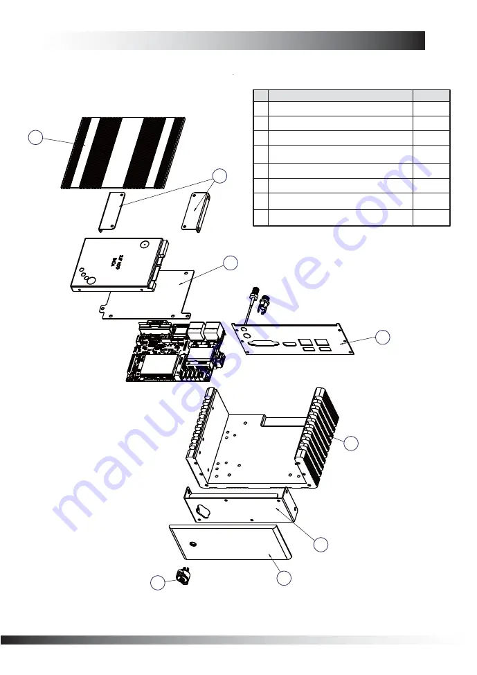
1-3 TERA Exploded Drawing
2
8
7
1
6
3
5
TOP COVER
BOTTOM COVER
POWER BOTTON
FRONT COVER
No
Name Q'ty
HDD BRACKET
TOP COVER BRACKET
FRONT FRAME
IO PANEL
Page 1: ...Assembly Guide...
Page 2: ...right sides of the chassis and remove the top cover Fig 1 1 3 Install the mini PCIe card into the slot at a 45 degree angle Fig 3 Fig 3 Fig 1 Fig 1 2 Remove the mini PCIe fixing screw from motherboard...
Page 3: ...d screw them with screws Fig 5 1 2 Installing for SATA HDD Version Fig 5 Fig 6 2 Connect the SATA Data Cable with HDD Fig 6 4 Connect the SATA Power Cable with motherboard Fig 8 Fig 8 3 Connect the SA...
Page 4: ...Fig 9 6 Place the HDD kit inside the system and tighten the screws manually Fig 10 Fig 10 Fig 11 7 Apply HDD thermal adhesive to HDD make sure don t stick on HDD track Fig 11 8 Put the cover back tigh...
Page 5: ...4 1 3 TERA Exploded Drawing 2 8 7 1 6 3 4 5 1 1 TOP COVER 1 2 BOTTOM COVER 2 3 POWER BOTTON 1 4 FRONT COVER No Name Q ty 5 6 7 8 HDD BRACKET 1 1 1 1 TOP COVER BRACKET FRONT FRAME IO PANEL...