


20
JCMOS1
:
CMOS clear select
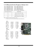
JVC1
:
COM1 voltage select
JVC2
:
COM2 voltage select
JVC3
:
COM3 voltage select
JVC4
:
COM4 voltage select
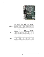
JVC5
:
COM5 voltage select
JVC6
:
COM6 voltage select
JVC7
:
COM7 voltage select
JVC8
:
COM8 voltage select
JVC9
:
COM9 voltage select
JVC10
:
COM10 voltage select
JVP1
:
LVDS Panel Inverter power select
JVL2
:
LVDS/eDP Panel power select
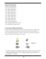
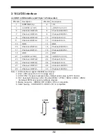
2-8 List of Jumpers
2-9 Jumper Setting Description
A jumper is ON as a closed circuit with a plastic cap covering two pins. A jumper is OFF
as an open circuit without the plastic cap. Some jumpers have three pins, labeled 1, 2,
and 3. You could connect either pin 1 and 2 or 2 and 3.The below
fi
gure 2.2 shows the
examples of different jumper settings in this manual.
All jumpers already have its default setting with the plastic cap inserted as ON,
or without the plastic cap as OFF. The default setting may be referred in this
manual with a " * " symbol .
Figure 2.2
Summary of Contents for CI170A
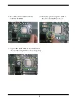
Page 8: ...3 2 1 3 1 2 3 Photo 1 Insert Unplug...
Page 20: ...15 2 3 Dimension CI170A C...


