background image


7


A.  Position one bracket to align with the holes on one side of the switch and secure it 

with the smaller bracket screws. Then attach the remaining bracket to the other 

side of the Switch. 

B.  After attached both mounting brackets, position the switch in the rack by lining up 

the holes in the brackets with the appropriate holes on the rack. Secure the Switch 

to the rack with a screwdriver and the rack-mounting screws. 

Note:

 For proper ventilation, allow about at least 4 inches (10 cm) of clearance on 

the front and 3.4 inches (8 cm) on the back of the Switch. This is especially 

important for enclosed rack installation. 


Power On                                   


Connect the power cord to the power socket on the rear panel of the Switch. The other 

side of power cord connects to the power outlet. The internal power supply of the 

Switch works with voltage range of AC power in the 100-240VAC, frequency 50~60Hz. 

Check the power indicator on the front panel to see if power is properly supplied. 

Summary of Contents for GSW-2453

Page 1: ...GSW 2453 Gigabit Chassis switch User Guide...

Page 2: ......

Page 3: ...ts 2 Ethernet Switching Technology 2 2 HARDWARE DESCRIPTION 4 Physical Dimension 4 Front Panel 4 LED Indicators 4 Rear Panel 6 Desktop Installation 6 Rack mounted Installation 6 3 NETWORK APPLICATION...

Page 4: ......

Page 5: ...t to end stations In general MDI means connecting to another Hub or Switch while MDIX means connecting to a workstation or PC Therefore Auto MDI MDIX means that you can connect to another Switch or wo...

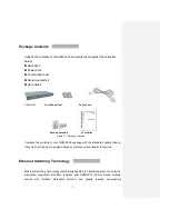
Page 6: ...Package Contents Compare the contents of your GSW 2453 package with the standard checklist above If any item is missing or damaged please contact your local dealer for service Ethernet Switching Tech...

Page 7: ...nt receiving port Auto negotiation regulates the speed and duplex of each port based on the capability of both devices Flow control allows transmission from a 1000Mbps node to a 100Mbps node without l...

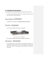
Page 8: ...e Front Panel of the GSW 2453 consists of 3 module slots Figure 2 1 The Front Panel of the GSW 2453 The modules in the picture are optional not including in the package LED Indicators The LED Indicato...

Page 9: ...ange In 100Mbps speed Off In 10Mbps or no device is connected LK ACT Green The port is connecting with the device Blinks The port is receiving or transmitting data Off No device attached Gigabit Mini...

Page 10: ...Make sure there is enough clearance around the Switch to allow attachment of cables power cord and allow air circulation Attaching Rubber Feet A Make sure mounting surface on the bottom of the Switch...

Page 11: ...screwdriver and the rack mounting screws Note For proper ventilation allow about at least 4 inches 10 cm of clearance on the front and 3 4 inches 8 cm on the back of the Switch This is especially impo...

Page 12: ...by directly connecting with 3 slot Gigabit Chassis s switch The switch automatically learns nodes address which are subsequently used to filter and forward all traffic based on the destination addres...

Page 13: ...s Look for loose or obviously faulty connections If they appear to be OK make sure the connections are snug IF that does not correct the problem try a different cable Non standard cables Non standard...

Page 14: ...ever if the Switch powers off after running for a while check for loose power connections power losses or surges at power outlet IF you still cannot resolve the problem contact your local dealer for a...

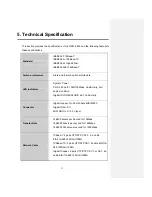
Page 15: ...rt 1000 100Mbps Link Activity Full duplex collision Gigabit SX LX MINI GBIC slot Link Activity Connector Gigabit copper RJ 45 with Auto MID MDI X Gigabit Fiber SC MINI GBIC LC 3 3 V type Transfer Rate...

Page 16: ...copper 4 MiniGBIC module MDU 2453TM MAC address 4K Packet Buffer 2 Mbits Dimensions 440mm W x 280mm D x 44mm H Power Supply 100 240VAC 50 60Hz 0 8A maximum Ventilation 2 x DC cooling fan Operating tem...

Reviews: