background image


  ENGLISH                                                                                   
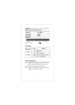
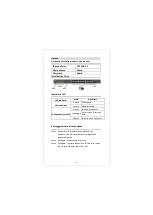
Manage the Switch Using Web Browser 

Installation


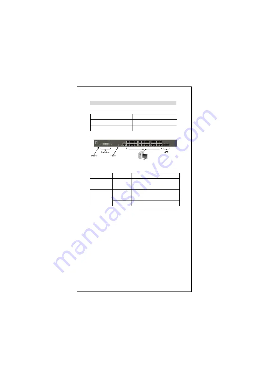
LED Indicator 


Connecting Equipment 

Step1.


Inspect the Power Adapter carefully, and make sure 
that it is properly connected to a power source. 

Step2.


Plug-in the Power Adapter to the Switch.   

Step3.


Connect  your  network  devices  with  the  switch  by 
using Ethernet cable. (e.g. Cat-5e) 


Default IP 

192.168.1.1 

Usermame   

admin 

Password 

admin 

LED Indicator 

Status 

Meaning 

Power 

On 

Power is on. 

Off 

Power is off. 

Link/Act 

On 

Port is connected 

Blinking  Transmitting / Receiving data 

Off 

Port is not connected 

Summary of Contents for GES-2451

Page 1: ...1 GES 2451 V2 26 Port Web Smart Gigabit Switch Quick Installation Guide English Deutsch Français Español Italiano Português ...

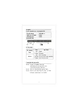
Page 2: ...connected to a power source Step2 Plug in the Power Adapter to the Switch Step3 Connect your network devices with the switch by using Ethernet cable e g Cat 5e Default IP 192 168 1 1 Usermame admin Password admin LED Indicator Status Meaning Power On Power is on Off Power is off Link Act On Port is connected Blinking Transmitting Receiving data Off Port is not connected ...

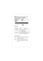
Page 3: ...hritt2 Verbinden Sie das Netzteil mit dem Switch Schritt3 Verbinden Sie weitere Geräte mit dem Switch unter Verwendung von Ethernet Kabeln z B Cat 5e Standard IP Adresse 192 168 1 1 Benutzername admin Kennwort admin LED Anzeige Status Bedeutung Power On Power ist an Off Power ist aus Link Aktivität On Port ist verbunden Blinken Senden Empfangen von Daten Off Port ist nicht verbunden ...

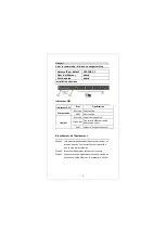
Page 4: ...ntation Étape2 Branchez l adaptateur secteur sur le switch Étape3 Connectez vos périphériques réseau au switch en utilisant un câble Ethernet Par exemple Cat 5e Adresse IP par défaut 192 168 1 1 Nom d utilisateur admin Mot de passe admin Indicateur DEL État Signification Alimentation Marche Sous tension Arrêt Hors tension Lien Act Marche Le port est connecté Clignotant Transmission Réception de do...

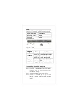
Page 5: ...onecte el adaptador de corriente al Switch Paso3 Conecte sus dispositivos de red con el switch mediante el uso de cable Ethernet Por ejemplo Cat 5e IP predeterminada 192 168 1 1 Nombre de usuario admin Contraseña admin Indicadores LED Estado Significado Potencia Encendido El dispositivo está encendido Apagado El dispositivo está apagado Estado de conexí ón Encendido El Puerto está conectado Interm...

Page 6: ...a sorgente elettrica Fase2 Collegare l alimentatore allo switch Fase3 Collegare il proprio dispositivo di rete allo switch con un cavo Ethernet ad es Cat 5e IP predefinito 192 168 1 1 Nome utente admin Password admin LED Indicator Stato Significato Alimentazione Acceso Alimentato Spento Non alimentato Collegamento attività Acceso La porta è connessa Lampeggio Trasmissione ricezione data Spento La ...

Page 7: ... tomada corretamente Passo2 Conecte o adaptador de energia ao Switch Passo3 Conecte seus dispositivos de rede no Switch utilizando cabos ethernet ex Cat 05e IP predefinido 192 168 1 1 Nome de utilizador admin Palavra passe admin LED indicador Status Significado Power Ligar Ligado Desligar Desligado Link Act Ligar Porta conectada Piscando Transmitindo Recebendo dados Desligar Porta não conectada ...

Page 8: ...8 ...

Page 9: ...9 ...

Page 10: ...10 ...

Page 11: ...11 ...

Page 12: ...12 ...

Page 13: ...13 ...

Page 14: ...14 ...

Reviews: