TMC 66
Test Monitoring Unit with integrated muting controller
607109 - 2010/08
Subject to change
without prior notice
C O N N E C T I N G A N D O P E R A T I N G I N S T R U C T I O N S
O r i g i n a l I n s t r u c t i o n s
Page 1: ...Monitoring Unit with integrated muting controller 607109 2010 08 Subject to change without prior notice C O N N E C T I N G A N D O P E R A T I N G I N S T R U C T I O N S O r i g i n a l I n s t r u...
Page 2: ...Notes regarding important pieces of information are marked by the symbol This connecting and operating instructions manual must be stored carefully It must be available for the entire operating time...
Page 3: ...Elements 13 4 Mounting of the Safety System 15 4 1 Mounting of the Test Monitoring Unit TMC 66 15 4 2 Mounting of the Single Beam Safety Light Barrier 15 4 2 1 Multi axis Installation 17 4 2 2 Muting...
Page 4: ...DEUTSCH ENGLISH FRAN AIS ITALIANO ESPA OL NEDERLANDS 6 Error Messages on the TMC 66 46 7 Technical Data 48 8 Appendix 50 8 1 Wiring diagram with Single Beam Safety Light Barrier and PLC as muting sen...
Page 5: ...he requirements concerning safety relevant parts of control units ISO 13849 1 The AOPD type 2 fulfills the requirements of category 2 acc to ISO 13849 1 A periodic function test has to detect malfunct...
Page 6: ...contactors are open Only then a new release is possible Restart interlock An equipment which disables the automatic restart of the machine after the sensor part has reacted during a dangerous part of...
Page 7: ...function Finger and hand protection The user is close to the hazardous area Access protection Access to the hazardous area is protected Presence detection A hazardous area which is completely surroun...
Page 8: ...ve 2004 108 EC Use of Work Equipment Directive 89 655 EEC supplemented by Directive 95 63 EC OSHA 1910 Subpart 0 Safety regulations Accident prevention regulations and safety rules Ordinance on Indust...
Page 9: ...s The Test Monitoring Unit is designed for installation in a cabinet or a protective housing with a protection rating of at least IP 54 The 24 V DC 20 power supply must guarantee safe isolation from t...
Page 10: ...witching contacts must be fused protected externally accord ing to the technical data The Test Monitoring Unit must be exchanged after a maximum of 20 years Repairs or the exchange of parts subject to...
Page 11: ...ot tested changes are made to the Test Monitoring Unit 2 5 Fields of Application The test monitoring unit TMC 66 may be used as isolating protective device for safeguar ding of hazardous areas on powe...
Page 12: ...on into the control has to be performed acc to the corresponding safety category acc to ISO 13849 1 The voltage free safety relay outputs can be directly used for shut down of the dangerous movement I...
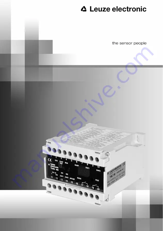
Page 13: ...1 Overview Display and Operating Elements LED 1 Status display protective field state LED 2 Status display start activation input LED 3 Status display start and restart interlock LED 4 Status display...
Page 14: ...screw driver size 1 into these carvings To remount the front screen simply press it into the fastening frame Observe the correct position of the code snugs The reset button can be activated through t...
Page 15: ...safety system 4 2 Mounting of the Single Beam Safety Light Barrier It is absolutely mandatory that the valid guidelines and standards are observed when mounting the single beam safety light barriers...
Page 16: ...he two beam AOPD and the test monitoring unit TMC 66 is 20 ms Application of the formula S K T C Assigned is Result S 1600 mm s 500 ms 20 ms 850 mm S 1682 mm S K T C S Safety distance between photoele...
Page 17: ...airs the single systems have to be mounted in different heights acc to EN 999 The number of used systems results from the corresponding type C standard or risk evaluation Deflection mirrors Applicatio...
Page 18: ...ures connected to reflection bypass Surfaces located parallel to the light beam can cause a reflection bypass An object within the light path is then no longer detected The photo electric sensor has t...
Page 19: ...paration signals Control 1 and Control 2 as well as two muting signals Start 1 and Start 2 for the muting function Note The TMC 66 is equipped with a direction detection to avoid manipulation The inpu...
Page 20: ...successful internal test the connected muting sensors are tested The TMC 66 takes over the control function The TMC 66 expects a reaction on the issued signal changes from the signals of Start 1 and S...
Page 21: ...of Control 2 signal change from High to Low Switching on of Start 2 activation of Start 2 signal change from Low to High As soon as the TMC 66 detects one of the mentioned signal changes the suppress...
Page 22: ...ough switching off of Control 1 Test Start 1 and Start2 internal test app 5 ms Muting test TMC internal selectable time period min 5 ms selectable time period End of muting Muting test of the sensors...
Page 23: ...trol 2 Fig 4 2 9 End of muting through switching off of Control 2 Test Start 1 and Start2 internal test app 5 ms Muting test TMC internal selectable time period min 5 ms selectable time period End of...
Page 24: ...o be fulfilled Signal Control 1 on LOW potential Signal Control 2 on LOW potential Photo electric sensor Start 1 free Signal Start 1 IN on HIGH potential Photo electric sensor Start 2 free Signal Star...
Page 25: ...tors In connection with driving motors and breaks the corresponding manuals have to be observed 5 1 Supply Wiring The test monitoring unit TMC 66 is supplied with 24V DC 15 Current consumption is max...
Page 26: ...tart and restart interlock the start input works as activation input As soon as a HIGH active signal is present at the start input and the protective field is free the safety outputs are closed Fig 5...
Page 27: ...e beam safety light barrier can be directly connected to terminal 1 on the TMC 66 The switching output of the receiver can be directly connected to terminal 2 The GND potential present on terminal 12...
Page 28: ...e TMC 66 terminal 1 activates the first photo electric sensor transmitter The receiver is activated via the first optical path and by using its output activates the second photo electric sensor transm...
Page 29: ...est of the muting sensors is performed as soon as both signals are connected The control signals have to be generated by two different signal sources That means either two contactor contacts or one co...
Page 30: ...ilure is erased after the defect lamp has been exchanged No muting state can be obtained if both lamps are defect or not connected One light signal Terminals 15 and 16 of the TMC 66 can also be connec...
Page 31: ...induced by the PLC The PLC is programmed to react on the test request of the TMC 66 The test of the PLC inputs and outputs is induced before every muting procedure while connecting the control signals...
Page 32: ...e integrated separately into the release circuits These can be connected to further components which are wired to a common EMERGENCY STOP device Integration with contactor monitoring The motor contact...
Page 33: ...sible only after removal of the failure in the output circuit 5 9 Wiring of the Signal Outputs Two signal outputs are integrated in the TMC 66 Both are HIGH active positive switching safety related tr...
Page 34: ...linking of the status outputs in the control unit the following system states can be detected 1 Safety on active Error inactive Normal operation of the TMC 66 no error detected 2 Safety on active Err...
Page 35: ...Remove the transparent front screen in order to change the settings The start and restart interlock can be switched off on the left switch switch 1 Start and restart interlock active contactor monito...
Page 36: ...toring unit TMC 66 can be released also in cases where e g after an emergency stop of the unit the single beam safety light barrier stays interrupted by remaining goods on the conveyor belt To enter t...
Page 37: ...the function of the single beam safety light barrier is cyclically tested every two seconds The free protective field is displayed by the green LED Activation is used green LED The safety output is c...
Page 38: ...In the waiting mode the single beam safety light barrier is free green LED Activation is not used The safety output is open This state is displayed by the red LED The yellow LED displays the lock of...
Page 39: ...tton the TMC 66 changes from test operation to protection mode The test operation is displayed through state 11 on the 7 segment display Protection mode In protection mode the function of the single b...
Page 40: ...function Eight muting phases can be differentiated if the TMC 66 is used with muting Phase 1 Activation of muting preparation through connection of the control signals Phase 2 Activation of muting th...
Page 41: ...Ds for control 1 and control 2 The 7 segment display changes from 21 to 22 The muting sensors Start 1 and Start 2 are tested in this state If an error occurs during the test this is displayed on the 7...
Page 42: ...3 Muting phase 3 The single beam safety light barrier is interrupted The indicator diode for Sensor goes off the LEDs for Control 1 and Control 2 remain active The 7 segment display changes from 23 to...
Page 43: ...nd Control 2 remain active The 7 segment display changes from 33 to 34 Muting phase 5 Continuation of muting through release of Start 1 The indicator diode for Start 1 lights up the LEDs for Control 1...
Page 44: ...trol 1 and Control 2 remain active The 7 segment display changes from 35 to 25 Muting phase 7 End of muting through release of Start 2 The indicator diode for Start 2 lights up the LEDs for Control 1...
Page 45: ...8 Basic state is again obtained through deactivation of control signals The indicator diodes for Control 1 and Control 2 go off The 7 segment display changes from 26 to 21 A new muting cycle can be st...
Page 46: ...ack circuit open Error in the wiring of the connected contactors check wiring Connected contactors defect welded contact replace contactor E2 Contactor monitoring deactivated contac tor contact of fee...
Page 47: ...1A or 2A or 3A Muting aborted A started muting procedure has not been completed if during a muting procedure the state of 1A 2A or 3A is displayed This message is alternatingly displayed with the indi...
Page 48: ...l 10 of the components have a failure to danger B10d Low load 20 20 million switching cycles DC 1 400 000 switching cycles AC 1 400 000 switching cycles Service life TM 20 years nop mean number of ann...
Page 49: ...contact 24 V max 2 A integrated spiral wound filament monitoring Contactor monitoring Optical coupler input HIGH active input current approx 10 mA Safety output voltage free make contact max current...
Page 50: ...cept is changed and the connected safety relevant components or protective devices are possibly not or insufficiently included in the safety circuit the user did not comply with the current safety reg...
Page 51: ...ix Leuze electronic TMC 66 51 TNT 35 7 24V DEUTSCH ENGLISH FRAN AIS ITALIANO ESPA OL NEDERLANDS You can also download this EC Declaration of Conformity from the Internet under http www leuze com inter...