background image

Electrical connection

Leuze electronic

CR 55

13

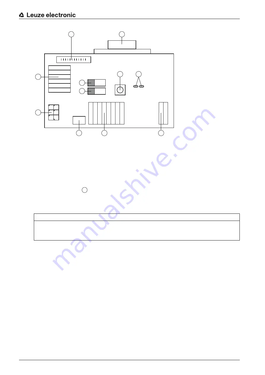
1

RS 232 connection

2

CR 50 connection

3

CR 100 or CR 55 connection

4

Molex Micro-Fit, 6-pin

5

USB connection

6

Connection to machine control, PLC, external voltage supply 5 VDC

7

External voltage supply 10 … 30 VDC

8

SWIN DIP switch (level for trigger button; 5 V if the scanner high switching input is active, GND if the 

low input is active)

9

USB/PWR DIP switch (USB position if voltage is supplied via USB; PWR position if voltage is sup

-

plied via 

)

10

Trigger button

11

Status LEDs

Figure 5.3: Connection options for MA-CR adapter circuit board

5.5

Cable lengths and shielding

The maximum cable length is 3 m.
Should a cable extension be necessary, make certain that the cables of the RS 232 interface are shielded.

NOTICE
Using the adapter circuit board

The MA-CR adapter circuit board is intended only for laboratory and test purposes and is not to be 

used for industrial applications!

1

2

10

11

3

4

8
9

5

6

7

7

Summary of Contents for CR 55 Series

Page 1: ...CR 55 Bar Code Reader O r i g i n a l o p e r a t i n g i n s t r u c t i o n s EN 2015 06 50129298 We reserve the right to make technical changes ...

Page 2: ...Leuze electronic CR 55 2 2015 Leuze electronic GmbH Co KG In der Braike 1 D 73277 Owen Germany Phone 49 7021 573 0 Fax 49 7021 573 199 http www leuze com info leuze de ...

Page 3: ...ng output 12 5 4 PC or terminal connection 12 5 5 Cable lengths and shielding 13 6 Configuration and diagnostic software Sensor Studio 14 6 1 System requirements 14 6 2 Installing Sensor Studio configuration software 15 6 2 1 Downloading configuration software 15 6 2 2 Installing the Sensor Studio FDT frame 15 6 2 3 Install the communication DTM and device DTM 15 6 2 4 Connecting bar code reader t...

Page 4: ... Care maintenance and disposal 26 9 1 Cleaning 26 9 2 Servicing 26 9 3 Disposing 26 10 Service and support 28 10 1 What to do should servicing be required 28 11 Technical data 29 11 1 General specifications 29 11 2 Reading fields 30 11 3 Dimensioned drawings 31 12 Ordering information and accessories 32 12 1 Type overview 32 12 2 Accessories 32 13 EC Declaration of Conformity 33 14 Appendix 34 14 ...

Page 5: ...assages with this symbol provide you with further information Symbols for action steps Text passages with this symbol instruct you to perform actions BCL Bar code reader CR CCD based bar code reader Code Reader DTM Software device manager Device Type Manager EMC Electromagnetic compatibility EN European standard FDT Software frame for management of device managers DTM Field Device Tool FE Function...

Page 6: ... the rules and regulations for occupational safety and safety at work They are familiar with the technical description of the device They have been instructed by the responsible person on the mounting and operation of the device Certified electricians Electrical work must be carried out by a certified electrician Due to their technical training knowledge and experience as well as their familiarity...

Page 7: ...ronic GmbH Co KG is not liable in the following cases The device is not being used properly Reasonably foreseeable misuse is not taken into account Mounting and electrical connection are not properly performed Changes e g constructional are made to the device ...

Page 8: ...aracteristics see chapter 11 3 1 2 Stand alone operation The bar code reader is operated as a stand alone single device It is equipped with a six wire cable with open ends for the electrical connection of the supply voltage the interface the switching input and the switching output 3 2 Performance characteristics High performance CCD scanner with front beam exit Compact design for simple integrati...

Page 9: ...s that indicates the readiness for operation and the read status of the bar code reader 3 5 1 LED indicators Two LEDs on the top of the device indicate the device and read status Table 3 1 LED indicators LED State Description PWR ON continuous light Voltage supply OK GOOD READ ON continuous light Reading successful ...

Page 10: ...oved past the reading window with a rotational angle of 10 to 15 the red light beam is narrowed down for its respective reading task in order to avoid reflections on shiny components α Azimuth angle β Angle of inclination γ Angle of rotation Recommended angle of rotation γ 10 Figure 4 1 Definition of the reading angles The size of the bar code module influences the maximum reading distance and the...

Page 11: ...active with the connection SW IN orange and GND violet We recommend wiring a 2 2 kΩ pull up resistor as defined cable termination see figure 5 1 CAUTION Safety notices The bar code reader is completely sealed and must not be opened Do not try to open the device under any circumstances as this voids both degree of protection IP 54 and the warranty Before connecting the device be sure that the suppl...

Page 12: ...at establishes the RxD TxD and GND connections between PC and bar code reader The RS 232 connection can be established in the following ways Direct connection of the bar code reader connection wires to the PC or terminal via its own connec tor Connection via an MA CR adapter circuit board To simplify the connection of the connection wires to the PC interface an adapter circuit board MA CR is avail...

Page 13: ...is active 9 USB PWR DIP switch USB position if voltage is supplied via USB PWR position if voltage is sup plied via 10 Trigger button 11 Status LEDs Figure 5 3 Connection options for MA CR adapter circuit board 5 5 Cable lengths and shielding The maximum cable length is 3 m Should a cable extension be necessary make certain that the cables of the RS 232 interface are shielded NOTICE Using the adap...

Page 14: ...l the communication and device DTM Communication and device DTM are included in the LeAnalysisCollectionSetup installation package Create CR 55 DTM in the project tree of the Sensor Studio FDT frame Connect bar code reader to PC see chapter 5 4 Activate service interface on bar code reader see chapter 7 3 2 6 1 System requirements To use the Sensor Studio configuration software you need a PC or la...

Page 15: ...he screen The installation wizard installs communication DTM and device DTM for CR 55 Administrator privileges on the PC are necessary for installing Sensor Studio The installation files of the Sensor Studio configuration software must be downloaded from the Internet at www leuze com For subsequent updates you can find the most recent version of the Sensor Studio installation software on the Inter...

Page 16: ... the bar code reader see chapter 7 3 2 The Sensor Studio configuration software is installed on the PC see chapter 6 2 Installing Sensor Studio configuration software Start the Sensor Studio configuration software by double clicking the Sensor Studio icon The mode selection of the Project Wizard is displayed Select the Device selection without communication connection offline configuration mode an...

Page 17: ...e manager DTM of the connected CR 55 starts with the offline view for the Sensor Studio configuration project Establish the online connection to the connected CR 55 In the Sensor Studio FDT frame click on the Establish connection with device button In the Sensor Studio FDT frame click on the Upload parameters to device button The current configuration data is displayed in the device manager DTM ...

Page 18: ...close the Sensor Studio configuration software Exit the program via File Exit Save the configuration settings as a configuration project on the PC You can open the configuration project again at later time via File Open or with the Sensor Studio Project Wizard 6 5 Configuration parameters In this chapter you will find information and explanations on the configuration parameters of the device manag...

Page 19: ...function Select the Help menu item in the menu Scan Mode Here you can select how a read process is to be activated LED Sleep Timeout Setting for the length of time after which the read LED in presentation mode is switched off Same Code Delay Length of time during which identical codes are output only once during multiple reading Inverse Code Reading of inverse codes General Settings Settings for t...

Page 20: ...are to be decoded are set We recommend enabling only the code types which are to actually be read with the corresponding element num bers Codes which are not enabled are not decoded Properties Symbologies Use the button to the right of the given code to select the code specific set tings Alternatively the property settings can be selected directly via the navigation tree under the Decode button Th...

Page 21: ...top bits the data bits the parity and various transmission modes here The desired acknowledgment settings are also to be set in this selection window 6 5 4 Maintenance software update Figure 6 7 Firmware reload With this tool new firmware files can first be selected for the CR 50 or CR 55 bar code reader then they can be loaded into the tool and subsequently executed ...

Page 22: ... code length is usually accomplished by using the Sensor Studio configuration software see chapter 6 The various parameter sets are explained in brief to understand what is happening during parameter setting see chapter 7 3 1 The parameters are then set using the buttons under CONFIGURATION To transfer the settings to the bar code reader its RS 232 settings must be set to the Service operating mod...

Page 23: ...r 5 4 PC or terminal connection Setting the required parameters is most easily carried out in the Service operating mode The operating mode Service provides the following defined operating parameters on the RS 232 inter face no matter how the bar code reader is configured for standard operation transmission rate 9600 baud no parity 8 data bits 1 stop bit Activating the service interface The servic...

Page 24: ...xt of this manual Most online commands are acknowledged by the device and any requested data returned For commands that are not acknowledged command execution can be observed or monitored directly on the device 8 2 General online commands Software version number Software reset Command H Software reset Parameter Activation Transmitted is H Command V Description Requests device version information P...

Page 25: ...e commands for system control Activating sensor input Deactivating sensor input Command Description The command activates decoding Parameter none Acknowledgment none Command Description The command deactivates decoding Parameter none Acknowledgment none ...

Page 26: ...efore mounting 9 2 Servicing Repairs to the device must only be carried out by the manufacturer For repairs contact your responsible Leuze electronic subsidiary or Leuze electronic customer service see chapter 10 9 3 Disposing For disposal observe the applicable national regulations regarding electronic components NOTICE Do not use aggressive cleaning agents Do not use aggressive cleaning agents s...

Page 27: ...r Braike 1 D 73277 Owen Germany 10 1 What to do should servicing be required Customer data please complete Leuze Service fax number 49 0 7021 573 199 NOTICE Please use this chapter as a master copy should servicing be required Enter the contact information and fax the form together with your service order to the fax number given below Device type Serial number Firmware Display messages LED states ...

Page 28: ...erleaved Code 39 Code 128 EAN 128 EAN UPC EAN Addendum Codabar Code 93 Interface type RS 232 or USB 2 0 virtual COM HID Baud rate 300 115200 baud Supply voltage 4 5 5 5 V DC Safety Class III PELV Protec tive Extra Low Voltage Notice For UL applications only for use in Class 2 cir cuits according to NEC Current consumption max 120 mA Ports 1 switching input 5 V DC 1 switching output 5 30V 20 mA LED...

Page 29: ...idity non condensing Electromagnetic compatibility EN 55022 IEC 62471 Conformity CE FCC Certifications UL 60950 1 CSA C22 2 No 60950 1 07 Please note that the actual reading fields are also influenced by factors such as labeling material printing quality scanning angle printing contrast etc and may thus deviate from the reading fields specified here The origin of the read distance always refers to...

Page 30: ...Technical data Leuze electronic CR 55 31 11 3 Dimensioned drawings all dimensions in mm Figure 11 2 Dimensioned drawing of CR 55 with front beam exit ...

Page 31: ...D line scanner USB interface fixed cable 1 8 m Part no Part designation Description 50128204 MA CR Adapter circuit board with spring terminals and 9 pin SUB D socket 50113396 KB DSub 9P 3000 RS 232 interconnection cable cable length 3 m USB driver for configuring the CR 55 scanner Download at www leuze com Sensor Studio configuration software Download at www leuze com see chapter 6 2 1 Downloading...

Page 32: ...of Conformity Leuze electronic CR 55 33 13 EC Declaration of Conformity The bar code readers of the CR 55 series have been developed and manufactured in accordance with the applicable European standards and directives ...

Page 33: ... Figure 14 1 Code type 01 Interleaved 2 of 5 Module 0 3 Figure 14 2 Code type 02 Code 39 Module 0 3 Figure 14 3 Code type 11 Codabar Module 0 3 Figure 14 4 Code 128 Module 0 3 Figure 14 5 Code type 08 EAN 128 SC 2 Figure 14 6 Code type 06 UPC A SC 3 Figure 14 7 Code type 07 EAN 8 ...

Page 34: ...Appendix Leuze electronic CR 55 35 SC 0 S Figure 14 8 Code type 10 EAN 13 Add on ...

Reviews: