background image

System overview

Leuze electronic

RS4/AS-i

7

T

N

T

 35/

7-

24V

DEUTSCH

ENGLISH

FRANÇAIS

IT

ALIANO

ESPAÑO

L

NEDERLANDS

2

System overview

The RS4 area scanner is an active optoelectronic protective device (AOPD) of type 3. It
polls the protective field that has been selected by the setting of parameters on a
continuous basis, and when the protective field is violated switches off its OSSD safety
switching outputs (OSSD = output signal switching device), so checking the hazardous
movement. While the system is in operation, it is possible to switch between up to four
parameterised protective fields and warning fields by means of local sensor signals.
Depending on the parameter settings, the scanner may emit a non-safety-related warning
signal if the front pane becomes too dirty and/or in the case of a warning field (that has
likewise been parameterised) being violated. 

In view of its integrated AS-i Interface, the RS4/AS-i can be connected to the AS-Interface
bus system. If a person or obstacle is situated within the protective fields that have been
defined earlier, a safety-related switching function will be triggered and the machine that is
protected by means of the AS-Interface and the AS-i safety monitor will be brought into a
safe state. This switching function will only be reset when the protective field is clear,
irrespective of the operating mode, which may be automatic or may involve acknowledge-
ment by way of the AS-i safety monitor. 

2.1

Short description of the RS4/AS-i

The RS4/AS-i area scanner sends out extremely short laser pulses, and measures the time
between the impacting of a pulse on an object and its being reflected back to the receiver of
the RS4/AS-i. The length of time enables the device to calculate the distance between the
object and the RS4/AS-i. 

The polling unit in the scanner rotates, and sends out / receives a laser pulse at intervals of
0.36°. In this way a sector of a circle of up to 190° can be polled, the RS4/AS-i being
located at the midpoint. The protective field that is to be monitored is limited by a user-
defined curve around the scanner, the maximum distance from this to the midpoint of the
scanner being 4 metres. If an object is detected between this boundary line and the
scanner, thus violating the protective field, the scanner will switch off its safety-related
OSSD output, and the status of the OSSDs will be transmitted to the AS-i safety monitor by
way of the AS-i system in the form of a cyclic data sequence; having been notified of the
violation of the protective field, the monitor will bring the hazardous movement to a halt. 

In addition to the safety-related protective field, a non-safety-related warning field can be
parameterised; when this is violated the system will not be switched off, but a warning
signal will be given. This will likewise be included in the data telegram that is exchanged
cyclically with the AS-i bus master and can be called up at will. 

Achtung!

Although the data transfer is safety-related, the warning signal should not be used in a
safety-related manner, as it is not delivered by the scanner as a safe signal.

The protective field and the warning field together constitute a pair of protective fields. They
are always activated jointly, and a maximum of four protective fields may be selected at any
time. All pairs of protective fields, as well as the permissible modes of switching between
them, will be adapted to the given application when the system is first put into operation.
When the system is operational, switching between protective field pairs is managed by
local sensor signals. 

Summary of Contents for AS-I

Page 1: ...ROTOSCAN RS4 AS i 607060 2009 03 Subject to change without prior notice A D D I T I O N A L I N F O R M A T I O N T O T H E C O N N E C T I N G A N D O P E R A T I N G I N S T R U C T I O N S ...

Page 2: ...re protected with the ROTOS CAN RS4 AS i laser scanner It is essential that all the instructions given in the Connecting and Operating Instructions and in the User Manual be observed especially those relating to safety The Connecting and Operating Instructions and the User Manual should be carefully looked after They must be available at all times throughout the period when the scanner is in use S...

Page 3: ...nisational measures 11 4 Construction assembly and connection to power supply AS i 13 4 1 Construction 13 4 2 Assembly 15 4 2 1 Calculating the safety distance total reaction time total response time for AS i applications 16 4 3 Electrical connection 17 4 3 1 Connections on the RS4 AS i 17 4 3 2 Guidelines for installation 18 4 3 3 Power supply to the RS4 AS i 18 5 Putting the system into operatio...

Page 4: ...IS ITALIANO ESPAÑOL NEDERLANDS 8 Standard delivery and order detalis 25 8 1 Standard delivery 25 8 2 Start up Set 25 8 3 Order details RS4 AS i and accesoires RS4 AS i 25 8 4 Order details accessories AS i Safety and AS i Safety Monitor 27 9 Declaration of conformity 28 ...

Page 5: ...ty The ROTOSCAN RS4 AS i laser scanner remote acting sensor was developed and manufactured with regard to the applicable European guidelines and standards An EC prototype test certificate valid for Europe as specified in DIN EN IEC 61496 1 and pr EN IEC 61496 3 has been conferred by TÜV Süddeutschland Group1 Zertifizierstelle Ridlerstr 65 D 80339 Munich GERMANY 1 3 Definition of terms on AS Interf...

Page 6: ...slave Slave which reads the safety related states On and Off of the sensor or command unit to which it is connected and transmits it to the master or safety monitor Safety related AS i slave Slave for connecting safety related sensors actuators and other devices Safety monitor Component which monitors the safety related slaves and the correct functioning of the network Slave Components for data tr...

Page 7: ...ngth of time enables the device to calculate the distance between the object and the RS4 AS i The polling unit in the scanner rotates and sends out receives a laser pulse at intervals of 0 36 In this way a sector of a circle of up to 190 can be polled the RS4 AS i being located at the midpoint The protective field that is to be monitored is limited by a user defined curve around the scanner the ma...

Page 8: ...1 The AS i safety monitor Within an AS i system corresponding to the configuration that the user has specified by means of the configuration software the AS i safety monitor keeps a check on the safety related AS i slaves that are allocated to it Depending on the device model up to two dependent or independent OSSDs with contactor monitoring are available In case of a Stop request or of a fault oc...

Page 9: ...ser data are defined as follows Only 1 bit of user information is transmitted The two possible states are interpreted as meaning free 1 and not free 0 Example Emergency stop not activated free hazardous movement approved Emergency stop activated not free hazardous movement not approved In the not free state the values 0 0 0 0 are statically registered in the 4 input bits of the AS i slave IC In th...

Page 10: ...nd Operating Instructions for the AS i safety monitor and the User Manual for the configuration and diagnosis software of the AS i safety monitor is also required asimon Configuration and Diagnostics Software Note Please have regard to the safety instructions and instructions for appropriate use of the equipment in chapter 3 of the Connecting and Operating Instructions for the RS4 4 Warning laser ...

Page 11: ...S i safety monitor is used AS i bus configurations that already exist as bus user devices can easily be added to and safety components with the appropriate AS i Safety at Work interface e g COMPACT AS i can easily be incorporated in the loop If the safety component does not have an AS i Safety at Work interface what are known as coupling modules e g the AS i coupling module ASKM1 can effect the co...

Page 12: ...bly of the end cap of the device on the connection side on either the transmitter or the receiver for an adjustment of the DIP switches if this should prove necessary see chapter 3 Assignment of the DIP switches Disposal Note Electronic scrap is special category waste and you should have regard to the regulations that apply locally to the disposing of such materials COMPACT AS i safety light curta...

Page 13: ...plug X1 PIN2 PIN4 Socket X3 is responsible for the external switching of the four protective field and warning field pairs Note For the wiring of the X3 socket please observe the notes on the switching of protective fields and warning fields in chapter 6 of the ROTOSCAN RS4 4 Connecting and Operating Instructions If only one protective field is required an M12 AC M12 15M bridge plug bridging PIN 1...

Page 14: ...ing socket To do this a standard AS Interface programming device for the definition of bus addresses should be used in conjunction with a special addressing socket programming cable see chapter 8 Advice on selection and ordering AS i safety accessories For parameterisation purposes and for local diagnosis of the RS4 a PC with the RS4soft software is connected to the top side of the RS4 AS i adapte...

Page 15: ...ny way This interface therefore corresponds in functional terms to the RS232 interface connected to the RS4 by means of SUB D plugs Note A comprehensive description of the software may be found in the RS4soft User Manual 4 2 Assembly Note See in this connection chapter 5 Planning and assembly instructions of the RS4 4 Connecting and Operating Instructions Note To assemble the RS4 AS i you should u...

Page 16: ...m of 40 ms when the full resources of the AS Interface system are installed with 31 slaves must be added to the response time T S K xT C C 1200 mm 0 4 H CMIN 850 mm HMIN 15 d 15 mm HMAX 1000 mm S is the minimum safety distance between protective field and danger zone in mm K is the speed of approach of the person or part of the body in mm ms T is the overtravel time of the machine the reaction tim...

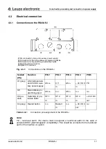
Page 17: ... on the RS4 AS i Socket plug Function PIN 1 PIN 2 PIN 3 PIN 4 PIN 5 X1 plug AS Interface data and 24 VDC auxi liary power supply AS i 0 V AS i 24 V DC FE in in X2 Bus address pro gramming input AS i n c AS i n c n c X3 so cket Switching of pro tective fields SF 1 SF 2 SF 3 SF 4 24 V DC in in in in out X4 plug Restart button n c Restart n c 24 V DC n c in out Table 4 3 1 Connection pin assignment o...

Page 18: ...X1 connection of the RS4 AS i to the AS i AC PDA1 A flat cable adapter there in turn the system can be provided with an earthing wire by way of two earthing springs on the modular screw plugs 4 3 2 Guidelines for installation Achtung The general safety instructions given in chapter 3 should be observed The electrical installation is to be carried out only by qualified and properly instructed profe...

Page 19: ...e data cable yellow and auxiliary power supply of 24 V DC black as well as with a 5 pole M12 connecting cable from the AS i adapter to the M12 connector socket X1 of the RS4 AS i 3 Check the 24 V power supply to the sensor The red LED on the RS4 AS i will light up 4 Check that the protective field of the RS4 AS i is clear The green LED will light up in about 20 seconds if the protective field is c...

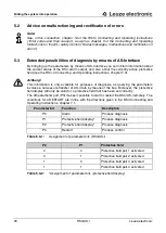
Page 20: ...3 Achtung This information is only available for purposes of diagnosis as querying the parameters involves a non secure transfer of AS i data by means of the bus Moreover the protective field display will only be valid for a protective field that has been set correctly The 4th parameter port P3 makes it possible to start or restart the RS4 AS i remotely The conditions for a RESTART are in line wit...

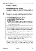
Page 21: ... system to a halt 2 Press the SERVICE button on the AS i safety monitor 3 Install the new AS i slave L AS i slaves supplied by Leuze electronic are set to the bus address 0 when leaving the factory When a slave is replaced the AS i master will program the replacement component automatically to the previous address of the defective component Re addressing of the replacement component to give the bu...

Page 22: ... mechanism Checks should be carried out once a year by the officer responsible for safety to ensure that the safety AS i system is functioning correctly that is to say that the AS i safety monitor will effect a safety switchoff when triggered by a safety related sensor that has been assigned to it e g RS4 AS i Achtung For this purpose the safety AS i slave should be activated once a year and its s...

Page 23: ...uit 400 mA Overload protection Medium time lag 2 A fuse Signal definition of the inputs High logical 1 16 30V Low logical 0 3 V Type of protection IP 65 Ambient operating temperature 0 C 50 C Ambient storage temperature 20 C 60 C Isolation class Protection class 2 Relative humidity 15 95 without condensation DIN 40040 Table 10 identifying letter E Weight ca 2 25 kg Dimensions 167 mm x 141 mm x 168...

Page 24: ... specifications and dimensional drawings 24 RS4 AS i Leuze electronic DEUTSCH ENGLISH FRANÇAIS ITALIANO ESPAÑOL NEDERLANDS Fig 7 0 1 Dimensional drawing of RS4 AS i a Axis of the rotating mirror b Scanning plane ...

Page 25: ...on with additional information to RS4 AS i the Connecting and Operating Instruction with additional information to RS4 PROFIsafe 8 3 Order details RS4 AS i and accesoires RS4 AS i Artikelbezeichnung Description Order No RS4 4 A1 RS4 AS i Laser scanner with AS i 580014 Zubehör RS4 AS i RS4 SWC RS4 start up set 970078 AC PDA1 A AS i adapter for bus connection and power sup py 580004 CB M12 2000 14 2...

Page 26: ...cloths soft and lint free 430400 RS4 Clean Set2 1000 ml Cleaning fluid for synthetic materials 100 cleaning cloths soft and lint free 430410 Test piece TB 70 500 Cylinder 500 mm in length 70 mm in diameter reflectance factor approx 1 8 50036433 Test piece TB 200 1000 Cylinder 1000 mm in length 200 mm in diameter reflectance factor approx 1 8 50036434 Artikelbezeichnung Description Order No ...

Page 27: ... plug socket 50024748 KB 095 2000 3AW Connection cable 2 m axial angled M12 plug socket 50024749 AS i Safety Monitor ASM1 1 AS i Safety monitor 1 relay output dual channel 580020 ASM1 2 AS i Safety monitor 2 relay output dual channel 580021 ASM1E 1 AS i Safety monitor aditional funtionality 1 relay output dual channel 580024 ASM1E 2 AS i Safety monitor aditional funtionality 2 relay output dual ch...

Page 28: ...acturer declares that the safety components of series RS4 AS i in the form in which they are marketed by us conform with the relevant basic safety and health requirements of the EC directives and that the standards were used in their design and construction Owen 01 02 2009 You can also download this EC Declaration of Conformity from the Internet under http www leuze com rotoscan Dr Harald Grübel G...

Reviews: