A.
12
B.
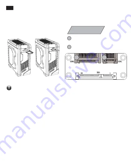
Be sure that the SATA cable and 4-pin power cable have been connected correctly, and all the related drivers of
motherboard have been installed. Then enable the “AHCI” function in the BIOS to activate the hot swap function to
complete the installation.
More information please refer to the instruction of your motherboard vendor.
Stellen Sie sicher, dass das SATA-Kabel und das 4-Pin-Stromkabel korrekt angeschlossen sind und
Sie alle notwendigen Mainboard-Treiber installiert haben. Schalten Sie im BIOS den AHCI-Modus ein, um die
Hot-Swap-Funktion zu aktivieren. Weitere Informationen entnehmen Sie bitte dem
Handbuch Ihres Mainboards.
3URV]ĊXSHZQLüVLĊF]\NDEHO6$7$RUD]NDEHO]DVLODMąF\3]RVWDá\SRGáąF]RQHSUDZLGáRZRL
wszystkie sterowniki
Sá\W\JáyZQHM]RVWDá\]DLQVWDORZDQHSRSUDZQLH3URV]ĊZ%,26LHZ\áąF]\üWU\E$+&,DE\XDNW\ZQLüIXQNFMĊKRW
VZDS:LĊFHMLQIRUPDFMLPRĪQD]QDOHĨüZLQVWUXNFMLREVáXJLSá\W\JáyZQHM
Assurez-vous que le câble SATA et le câble d'alimentation à 4 broches sont bien connectés et que tous les pilotes
liés à la carte mère ont été installés. Ensuite, activez la fonction "AHCI" dans le BIOS pour activer la fonction Hot
Swap pour terminer l'installation. Pour plus d'informations, référez-vous à l'instruction de votre carte mère.
SATA
ケーブル及び
4
ピン電源ケーブルがしっかり接続されていることと、マザーボードに全ての関連する駆動ドライバ
ーがインストールされたことを確認してください。そして、
BIOS
の中にある
"AHCI"
機能を有効にし、ホットスワップ機能
が利用可能となります。詳細情報をご利用の場合は、マザーボードメーカーの指示をご参考ください。
請確認SATA線材及SATA電源線均已正確連接,主機板相關驅動程式均已安裝完畢。 並進入BIOS
啟
用支援硬
碟
熱插拔
之”AHCI”功能,以完成安裝。
/ŶƐƚĂůůĂƟŽŶ
Connect SATA power connector to
power supply
Connect SATA cable to motherboard
2
1
2
1
hƐŝŶŐƚŚĞϮ͘ϱΗŚŽƚƐǁĂƉĚŽĐŬ
Notice:
2.7
,ŽǁƚŽhƐĞ,ŽƚͲƐǁĂƉŽĐŬ
ĞĚŝĞŶƵŶŐĚĞƌ,ŽƚͲ^ǁĂƉͲŽĐŬŝŶŐƐƚĂƟŽŶĂƵĨĚĞƌ
KďƐųƵŐĂƐƚĂĐũŝĚŽŬƵũČĐĞũnjĨƵŶŬĐũČŚŽƚƐǁĂƉ
ŽŵŵĞŶƚƵƟůŝƐĞƌ,ŽƚͲƐǁĂƉŽĐŬ
アドオンカードの取り付け
熱插拔硬碟使用
Summary of Contents for Lenyx LPC801 Series
Page 1: ...User s Manual Handbuch Instrukcja ob Deutsch P D LPC801 Series...
Page 4: ...3 Right side...
Page 5: ...4 h K D W h h W Reset Controller d...
Page 7: ...6 2 1 How to R ove Both Side P nt w boczn ch Chapter 2 Mont g Instruk nt u 1 2 3...
Page 8: ...7 2 2 D D 2 3 W E...
Page 9: ...8 How to Inst rds Inst k rozszerz 2 4 A B 1 2...
Page 10: ...9 C Z h Press Press Press Press...
Page 11: ...10 Inst w o t czn ch 2 5 A C B UNLOCKED LOCKED...
Page 14: ...13 d Z Z Z Z 2 8 A B C...
Page 15: ...14 D E F Notice d...
Page 16: ...15 W h t Notice Notice...
Page 17: ...16 How to Inst S st F Inst wen tor w s st...
Page 20: ......


