Leonton REG5-2602-2C Series User Manual Download Page 5


Overview 

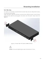
This  series  is  rated  IP40  and  installation  by  Rack-Mount.  Each  unit  of  this  industrial  gigabit 

managed  Ethernet  switch  series  has  24*10/100/1000Tx  and  2  Gigabit  combo  ports 

(2*10/100/1000Tx  RJ45  or  2*100/1000  SFP  slots),  suitable  for  applications  that  require  high 

bandwidth and long distance communication. 

In  order  to  prevent  unregulated  voltage,  this  series  provides  high  EFT  and  ESD  protection.  This 

also allows it to function in harsh environments, as well as support power redundancy with a dual 

power  input  design  with  reverse  polarity  protection.  The  built-in  relay  warning  function  alerts 

users about occurring power failures. 

With  one  model  having  an  operating  temperature  of  -10  to  65°C,  and  another  with  a  wide 

operating  temperature  of  -40  to  75°C,  this  series  is  designed  to  meet  any  needs  for  industrial 

automation, outdoor application and harsh environments.   


Software Features 

Software Features 


Layer 3 Switching 

Static Routes 

Management 

CLI, Http, Https, SNMP, SSH, Telnet 

Security 

Access Management, ACL, ARP Inspection, DHCP Snooping, IP Source 

Guard, Multiuser Account, Port Security Limit Control, RADIUS, 

, 802.1Q VLAN, IP Subnet-based VLAN, MAC-based VLAN, 

Private VLAN, Protocol-based VLAN, GVRP 

Green Ethernet 

IEEE 802.3az EEE (Energy Efficient Ethernet) 

Network Reliability 

STP, RSTP, MSTP, ERPS (G.8032) 

Multicast 

IGMP snooping, MLD snooping, MVR 

Traffic Control 

LACP, QoS (CoS/ToS) 

Monitor 

LLDP, LLDP-MED, Port Mirroring, RMON, MIB, sFlow, Syslog Server 

DHCP 

DHCP Server/Client/Relay/Snooping 

Other 

ICMP Ping, ICMPv6 Ping, Loop Protection, Storm Protection, NTP Client 

PoE Management 

(For PoE Models) 

PoE Alive Check, PoE Power Budget Managed, PoE Scheduled 


Hardware Features 

Interface & Performance 


All Copper ports support auto MDI/MDI-X function 


Embedded  24*10/100/1000Tx  and  2*gigabit  combo  ports  (2*10/100/1000Tx  copper  ports 

Summary of Contents for REG5-2602-2C Series

Page 1: ...LEONTON REG5 2602 2C Series REG5 2602 2C REG5 2602 2C T User Manual...

Page 2: ...t not limited to the implied warranties of merchantability and fitness for a particular purpose LEONTON Technologies Co Ltd may make improvements and or changes to the product and or specifications of...

Page 3: ...the equipment off and on the user is encouraged to try to correct the interference by one or more of the following measures Reorient or relocate the receiving antenna Increase the separation between t...

Page 4: ...ption 4 Physical Dimensions 4 Front Panel 5 Rear Panel 5 LED Indicators 5 Ethernet Ports 7 Cabling 8 Wiring the Power Input 10 Wiring the Fault Alarm Contact 11 Grounding Note 11 Mounting Installation...

Page 5: ...ndustrial automation outdoor application and harsh environments Software Features Software Features Layer 3 Switching Static Routes Management CLI Http Https SNMP SSH Telnet Security Access Management...

Page 6: ...ure model T 40 C 75 C Case Installation IP 40 protection Installation in a Pollution Degree 2 industrial environment Rack mount design Package Contents 1 REG5 2602 2C T 2 Rack mounting brackets and sc...

Page 7: ...3 Figure 1 2 Hot Surface Warning Label...

Page 8: ...4 Hardware Description Physical Dimensions Figure 2 1 below shows the physical dimensions of REG5 2602 2C series W x D x H is 440mm x 200mm x 44mm Figure 2 1 REG5 2602 2C Series Physical Dimensions...

Page 9: ...REG5 2602 2C series switch that is equipped with one AC power inputs socket 90 264VAC and one 2 pin terminal block for relay output Figure 2 3 The Back Panel of REG2 2602 2C Series LED Indicators The...

Page 10: ...onnected to network 1000Mbps Flashing Networking is active Off Not connected to network 10 100 LAN Port 1 24 Green On Connected to network 10 100Mbps Flashing Networking is active Off Not connected to...

Page 11: ...onnections Auto MDI MDIX means that the switch can connect to another switch or workstation without changing the straight through or crossover cabling See the figures as below for straight through and...

Page 12: ...45 port connections The cable between the switch and the link partner switch hub workstation etc must be less than 100 meters 328 ft long The small form factor pluggable SFP is a compact optical tran...

Page 13: ...C connector into the transceiver as shown below in Figure 2 9 Figure 2 9 LC Connector to the Transceiver To remove the LC connector from the transceiver please follow the steps shown below Step 1 Pres...

Page 14: ...as shown below in Figure 2 4 Figure 2 4 Pull Out from the SFP Module Wiring the Power Input Caution Please follow the below steps to insert the power wire Step 1 Insert the AC power cable into the uni...

Page 15: ...fault alarm contact is shown below in Figure 2 6 Figure 2 6 Wiring the Fault Alarm Contact Caution The wire gauge for the terminal block should range between 12 24 AWG Grounding Note Grounding and wir...

Page 16: ...mounting switch Locate one plate to align with the holes on one side of the switch and secure it with the plate screws and then attach the remaining plate to the other side of the switch Please refer...

Page 17: ...llation Step 3 Power on the industrial Ethernet switch and then the power LED light will turn on If you need help on how to wire power please refer to the Wiring the Power Inputs section Please refer...

Page 18: ...l as other cables Be careful when handling them so as to not trip over Do not under any circumstance insert foreign objects of any kind into the heat dissipation holes located in the different faces o...

Page 19: ...ssist in identifying problems the switch can be easily monitored with the LED indicators which help to identity if any problems exist Please refer to the LED Indicators section for LED light indicatio...

Reviews: