13.5.3.1
Basic setting
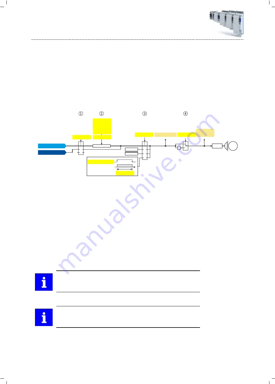
The following parameters must be set for the activation and basic setting of the holding brake
control.
Details
The following settings are possible:
•
Brake mode
①
•
For the automatic operation:
②
-
Brake release time and brake application time
-
Torque feedforward control
•
Test Brake control
③
•
Brake polarity
④
Device status
0x2820:020, Bit 1
t
0x2820:019
1
0
Start
Stop
0x2820:021
0x2820:010
0x2820:009
0x2820:003
0x2820:002
0x2820:015
0x2820:004
0x6040:000, Bit16
Auto
0x2820:001
1
0
2
1
0
1
X106
0x2820:005
0x6041, Bit 14
2
3
0x2820:011
1
0
M
Diagnostic parameters:
•
Display status of the automatic brake identification:
•
Display signal of the brake logic before the inversion:
•
Display status of the holding brake:
•
Manual control via the control word. Das control word depends on the technology applica-
tion :
•
Technology application CiA 402:
Bit 14
•
Speed Control technology application: 0x5030:010 Bit 14
•
0: Close holding brake
•
1: Release holding brake
•
Control via device state machine (automatic operation):
-
The holding brake is controlled as a function of the device state.
-
A torque feedforward control is possible.
The torque is precontrolled for one second. During this time, the actual torque
must have reached 90 % of the setpoint torque, otherwise an error is triggered.
-
Response times of the holding brake during release and application can be compensa-
ted for.
In the event of an error or when STO ("SafeTorqueOff") is activated, the brake is
applied immediately without considering the set brake application time. The
inverter immediately changes to the switch-on disabled state.
•
No brake connected (off):
-
holding brake control, automatic brake identification and brake monitoring are deacti-
vated.
Configuring the motor control
Parameterisable motor functions
Holding brake control
254
Summary of Contents for i950 Series
Page 1: ...Inverters i950 servo inverters Commissioning EN ...
Page 2: ......
Page 497: ......
Page 498: ......
Page 499: ......


