


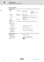

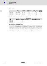


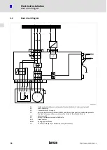


Electrical installation
Power terminals
l
67
EDKLCFH3024−EER DE/EN 2.0
4.3
Power terminals
}
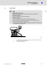
Danger!
Uncontrolled motor movements can occur
If the motor cable is damaged, a short circuit between the brake control cables
and the motor cables can cause motor movements with low torque.
Possible consequences:
ƒ
Personnel in the vicinity of the motor can be injured.
Protective measures:
ƒ
Install motor cable in a protected way (e.g. in a cable duct).
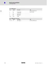
X10 − Mains connection
Pin
Connection
Description
Data
Connector: male, Harting HAN−Modular
a1
L1
Phase L1
3/PE AC 320 V − 0% ... 550 V + 0%
45 Hz − 0 % ... 65 Hz + 0 %
Max. 6 mm
2
a2
L2
Phase L2
a3
L3
Phase L3
+
PE
PE conductor
X11 − 24 V DC connection
Pin
Connection
Description
Data
Connector: male, Harting HAN−Modular
b1
24 V DC
Control electronics voltage supply (safely
isolated to EN 50178)
Safely separated power supply unit
(SELV / PELV)
+24 V DC
(+19.2 V DC − 0 % ... + 28.8 V DC + 0 %)
Min. 1.9 A
Max. 4.4 A
b2
n. c.
Not assigned
b3
GND
Reference potential
Summary of Contents for ELCAFHI 4E34NNER Series
Page 3: ...ELCAFHIE34NNER_001A ...


