background image

37

Lenovo Y40-70/Y40-80/Y50-70/Y50-80/Y50-70 Touch/ Y50-80 Touch

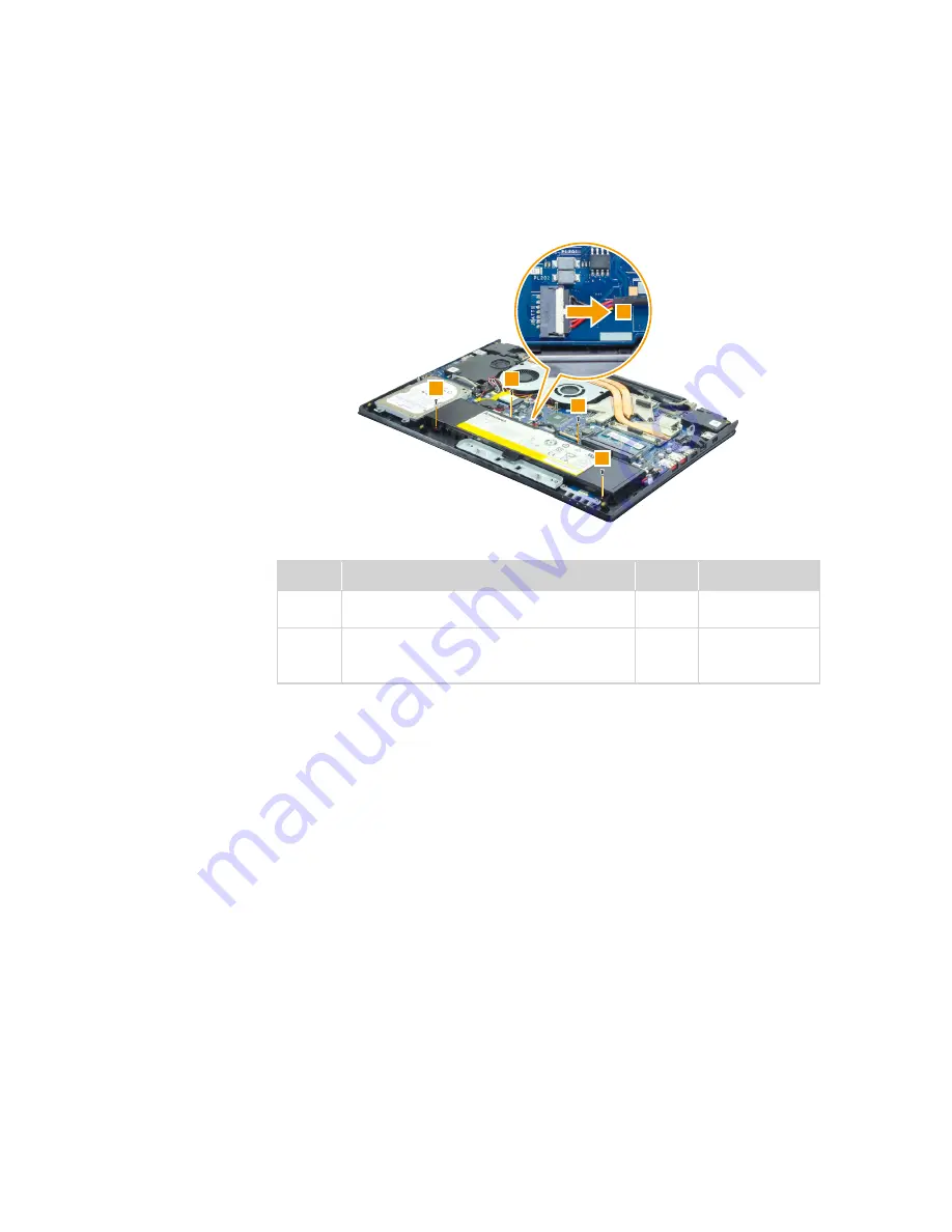
Figure 2. Removal steps of battery pack (continued)

Y50-70/Y50-80/Y50-70 Touch/Y50-80 Touch

Step

Screw (quantity)

Color

Torque

2

M2.0 × 3.0 mm, flat-head, nylok-coated (5) 

Battery TO Logic UP (Y40-70/Y40-80)

Black

2.0 kgf*cm

2

M2.5 × 5.0 mm, flat-head, nylok-coated (4) 

BATT to LOGIC (Y50-70/Y50-80/ 

Y50-70 Touch/Y50-80 Touch)

Black

2.5 kgf*cm

Summary of Contents for Y40-70

Page 1: ...Lenovo Y40 70 Y40 80 Y50 70 Y50 80 Y50 70 Touch Y50 80 Touch Hardware Maintenance Manual ...

Page 2: ...0 70 Touch Y50 70 Touch The illustrations used in this manual are for Lenovo Y50 70 Touch unless otherwise stated First Edition Mar 2014 Copyright Lenovo 2014 All rights reserved LIMITED AND RESTRICTED RIGHTS NOTICE If data or software is delivered pursuant a General Services Administration GSA contract use reproduction or disclosure is subject to restrictions set forth in Contract No GS 35F 05925...

Page 3: ...word 24 Power management 25 Screen blank state 25 Putting the computer to sleep or shutting it down 25 Putting your computer to sleep 25 Shutting down the computer 25 Lenovo Y40 70 Y40 80 Y50 70 Y50 80 Y50 70 Touch Y50 80 Touch 26 Specifications 26 Status indicators 28 Fn key combinations 30 FRU replacement notices 31 Screw notices 31 Removing and replacing an FRU 32 1010 Base cover 33 1020 Batter...

Page 4: ...de general information guidelines and safety information required for servicing computers The product specific section includes service reference and product specific parts information Important This manual is intended only for trained servicers who are familiar with Lenovo products Use this manual to troubleshoot problems effectively Before servicing a Lenovo product make sure to read all the inf...

Page 5: ... Lenovo Y40 70 Y40 80 Y50 70 Y50 80 Y50 70 Touch Y50 80 Touch computer General safety on page 2 Electrical safety on page 3 Safety inspection guide on page 5 Handling devices that are sensitive to electrostatic discharge on page 6 Grounding requirements on page 6 Safety notices multilingual translations on page 7 Laser compliance statement on page 14 ...

Page 6: ...r parts in a safe place away from all personnel while you are servicing the machine Keep your toolcase away from walk areas so that other people will not trip over it Do not wear loose clothing that can be trapped in the moving parts of the machine Make sure that your sleeves are fastened or rolled up above your elbows If your hair is long fasten it Insert the ends of your necktie or scarf inside ...

Page 7: ...x in the off position If you need to work on a machine that has exposed electrical circuits observe the following precautions Ensure that another person familiar with the power off controls is near you Attention Another person must be there to switch off the power if necessary Use only one hand when working with powered on electrical equipment keep the other hand in your pocket or behind your back...

Page 8: ...reflective surface of a plastic dental mirror The surface is conductive such touching can cause personal injury and machine damage Do not service the following parts with the power on when they are removed from their normal operating places in a machine Power supply units Pumps Blowers and fans Motor generators and similar units This practice ensures correct grounding of the units If an electrical...

Page 9: ...e or missing hardware To determine whether there are any potential unsafe conditions use the following checklist at the beginning of every service task Begin the checks with the power off and the power cord disconnected Checklist 1 Check exterior covers for damage loose broken or sharp edges 2 Turn off the computer Disconnect the power cord 3 Check the power cord for a A third wire ground connecto...

Page 10: ...ap against your skin to eliminate static on your body Prevent the part from touching your clothing Most clothing is insulative and retains a charge even when you are wearing a wrist strap Use the black side of a grounded work mat to provide a static free work surface The mat is especially useful when handling ESD sensitive devices Select a grounding system such as those listed below to provide pro...

Page 11: ... Austausch der Computer wieder angeschlossen wird muß sichergestellt werden daß keine Schrauben Federn oder andere Kleinteile fehlen oder im Gehäuse vergessen wurden Der Computer muß geschüttelt und auf Klappergeräusche geprüft werden Metallteile oder splitter können Kurzschlüsse erzeugen Prima di accendere l elaboratore dopo che é stata effettuata la sostituzione di una FRU accertarsi che tutte l...

Page 12: ... und Cadmium enthalten Sie darf nicht zerlegt wiederaufgeladen kurzgeschlossen oder Feuer oder Wasser ausgesetzt werden Bei der Entsorgung die örtlichen Bestimmungen für Sondermüll beachten Beim Ersetzen der Bereitschafts oder Systembatterie nur Batterien des Typs verwenden der in der Ersatzteilliste aufgeführt ist Der Einsatz falscher Batterien kann zu Entzündung oder Explosion führen Alcune batt...

Page 13: ...eschlossen oder Feuer oder Wasser ausgesetzt werden Bei der Entsorgung die örtlichen Bestimmungen für Sondermüll beachten Beim Ersetzen der Batterie nur Batterien des Typs verwenden der in der Ersatzteilliste aufgeführt ist Der Einsatz falscher Batterien kann zu Entzündung oder Explosion führen La batteria contiene piccole quantità di nichel Non smontarla gettarla nel fuoco o nell acqua né cortoci...

Page 14: ...rufen Batterien dieses Typs dürfen nicht aufgeladen zerlegt über 100 C erhitzt oder verbrannt werden Auch darf ihr Inhalt nicht mit Wasser in Verbindung gebracht oder der zur richtigen Polung angebrachte Verbindungsstecker entfernt werden Bei der Entsorgung die örtlichen Bestimmungen für Sondermüll beachten Beim Ersetzen der Batterie nur Batterien des Typs verwenden der in der Ersatzteilliste aufg...

Page 15: ...irm besteht aus Glas und kann zerbrechen wenn er unsachgemäß behandelt wird oder der Computer auf den Boden fällt Wenn der Bildschirm beschädigt ist und die darin befindliche Flüssigkeit in Kontakt mit Haut und Augen gerät sollten die betroffenen Stellen mindestens 15 Minuten mit Wasser abgespült und bei Beschwerden anschließend ein Arzt aufgesucht werden Nel caso che caso l LCD si dovesse rompere...

Page 16: ...orted or grounded battery can produce enough current to burn personnel or combustible materials Bien que le voltage des batteries principales soit peu élevé le court circuit ou la mise à la masse d une batterie peut produire suffisamment de courant pour brûler des matériaux combustibles ou causer des brûlures corporelles graves Obwohl Hauptbatterien eine niedrige Spannung haben können sie doch bei...

Page 17: ...et déconnectez tous les cordons d interface Die Stromzufuhr muß abgeschaltet alle Stromkabel aus der Steckdose gezogen der Akku entfernt und alle Verbindungskabel abgenommen sein bevor eine FRU entfernt wird Prima di rimuovere qualsiasi FRU spegnere il sistema scollegare dalle prese elettriche tutti i cavi di alimentazione rimuovere la batteria e poi scollegare i cavi di interconnessione Antes de ...

Page 18: ...adjustments or performance of procedures other than those specified herein might result in hazardous radiation exposure O uso de controles ajustes ou desempenho de procedimentos diferentes daqueles aqui especificados pode resultar em perigosa exposição à radiação Pour éviter tout risque d exposition au rayon laser respectez les consignes de réglage et d utilisation des commandes ainsi que les proc...

Page 19: ...luz Rayonnement laser si carter ouvert Évitez de fixer le faisceau de le regarder directement avec des instruments optiques ou de vous exposer au rayon Laserstrahlung bei geöffnetem Gerät Nicht direkt oder über optische Instrumente in den Laserstrahl sehen und den Strahlungsbereich meiden Kinyitáskor lézersugár Ne nézzen bele se szabad szemmel se optikai eszközökkel Kerülje a sugárnyalábbal való é...

Page 20: ...vice drivers are posted on the customer support site http support lenovo com Strategy for replacing FRUs Before replacing parts Make sure that all software fixes drivers and BIOS downloads are installed before replacing any FRUs listed in this manual After a system board is replaced ensure that the latest BIOS is loaded to the system board before completing the service action To download software ...

Page 21: ...onfiguration settings using the View Configuration option then when service has been completed verify that those settings remain in effect Strategy for replacing a hard disk drive Always try to run a low level format before replacing a hard disk drive This will cause all customer data on the hard disk to be lost Make sure that the customer has a current backup of the data before performing this ac...

Page 22: ...ransit to RoHS compliance well before the implementation date and expects its suppliers to be ready to support Lenovo s requirements and schedule in the EU Products sold in 2005 and 2006 will contain some RoHS compliant FRUs The following statement pertains to these products and any product Lenovo produces containing RoHS compliant FRUs RoHS compliant FRUs have unique FRU part numbers Before or af...

Page 23: ...ence might have been altered If you select an incorrect drive data or programs might be overwritten Replace an FRU only with another FRU of the correct model When you replace an FRU make sure that the machine model and the FRU part number are correct by referring to the FRU parts list An FRU should not be replaced just because of a single unreproducible failure Single failures can occur for a vari...

Page 24: ...s covered under the warranty by referring to the following list The following are not covered under warranty LCD panel cracked from the application of excessive force or from being dropped Scratched cosmetic parts Distortion deformation or discoloration of the cosmetic parts Plastic parts latches pins or connectors that have been cracked or broken by excessive force Damage caused by liquid spilled...

Page 25: ...cord of the AC adapter for correct continuity and installation If the computer does not charge during operation go to Checking operational charging To check the AC adapter follow the steps below 1 Unplug the AC adapter cable from the computer 2 Measure the output voltage at the plug of the AC adapter cable See the following figure 1 2 9ROWDJH 9 3LQ Note Output voltage for the AC adapter pin No 2 m...

Page 26: ...rging does not start until the Power Meter shows that less than 95 of the total power remains under this condition the battery pack can charge to 100 of its capacity This protects the battery pack from being overcharged or from having a shortened life To check your battery move your cursor to the Power Meter icon in the icon tray of the Windows taskbar and wait for a moment but do not click it and...

Page 27: ... pre installed OneKey Recovery System In order to save application files and the initial backed up files of the system the hard disk in a Lenovo computer includes a hidden partition when it is shipped If you need to restore the system to the point of your first boot up just enter Lenovo OneKey Recovery System and run System Recovery For details of OneKey Recovery System see the User Guide for Leno...

Page 28: ...ere are two hard disk passwords HDPs User HDP for the user Master HDP for the system administrator who can use it to get access to the hard disk drive even if the user has changed the user HDP Attention If the user HDP has been forgotten check whether a master HDP has been set If it has it can be used for access to the hard disk drive If no master HDP is available neither Lenovo nor Lenov authoriz...

Page 29: ...short time put the computer to sleep When the computer is in sleep mode you can quickly wake it to resume use bypassing the startup process To put the computer to sleep do one of the following Close the display panel Press the power button Open the Charms and then select Settings Power Sleep Attention Wait until the power indicator light starts blinking indicating that the computer is in sleep mod...

Page 30: ...0 Y50 70 Y50 80 Y50 70 Touch Y50 80 Touch Table 1 Specifications Feature Description Processor See the system properties of your computer you can do this as follows Open the Control Panel and then select System Bus architecture 1600Mhz DDR3L SDRAM PCI Express bus 2 0 Serial ATA 6Gb s USB3 0 HDMI 1 4 eDP 1 3 Graphic memory chip NV N15P GX AMD Venus XTX Display 14 0 16 9 1 920 1 080 pixels FHD 15 6 ...

Page 31: ...Feature Description Ethernet on the system board 10 100 1 000 Mbps Bluetooth wireless Combined in combo card Keyboard 6 row ISO full size keyboard Touchpad Multi touch type Integrated camera HD 720p Battery 4 cell 48 Wh 54 Wh AC adapter 20 V 90 W or 135 W Pre installed operating system Windows 8 1 ...

Page 32: ...e Charging The battery has more than 80 charge Discharging The battery has more than 20 charge On solid amber Discharging The battery has between 5 and 20 charge Blinking slowly white Charging The battery has between 20 and 80 charge When the battery reaches 80 charge the light will stop blinking However charging will continue until the battery is fully charged Blinking slowly amber Charging The b...

Page 33: ...uch Indicator Indicator status Charge status Meaning 3 Touchpad On solid white The touchpad is enabled Off The hard disk drive is reading or writing data 4 Hard Disk Drive Blinking The hard disk drive is reading orwriting data Table 2 Status indicators continued ...

Page 34: ...ane mode Fn F6 Enables disables the touchpad Fn F9 Opens the Settings charm Fn F10 Opens the Search charm Fn F11 Displays current apps Fn PrtSc Activates the system request Fn Insert Lenovo Y50 70 Y50 80 Y50 70 Touch Y50 80 Touch Fn PgUp Lenovo Y40 70 Y40 80 Enables disables the scroll lock Fn Home Activates the pause function Fn End Activates the break function Fn PgDn LenovoY40 70 Y40 80 Activat...

Page 35: ...ag Carefully remove screws for reuse when replacing FRUs Use a torque screwdriver if you have one Tighten screws as follows Plastic to plastic Turn an additional 90 after the screw head touches the surface of the plastic part more than 90 Cross section Logic card to plastic Turn an additional 180 after the screw head touches the surface of the logic card more than 180 Cross section Torque driver I...

Page 36: ...llow any of the notes that pertain to replacement For information about connecting and arranging internal cables see Locations on page 81 8 When replacing an FRU use the correct screw as shown in the procedures DANGER Before removing any FRU turn off the computer unplug all power cords from electrical outlets remove the battery pack and then disconnect any of the interconnecting cables Attention A...

Page 37: ...se cover Y40 70 Y40 80 Remove the screws 1 and 2 Step Screw quantity Color Torque 1 M2 0 11 mm flat head nylok coated 3 LOGIC LOWER TO LOGIC UPPER Black 2 0 kgf cm 2 M2 0 5 0 mm flat head nylok coated 8 LOGIC LOWER TO LOGIC UPPER Black 2 0 kgf cm Remove the base cover in the directions shown by arrows 3 and 4 ...

Page 38: ...Figure 1 Removal steps of base cover continued Y50 70 Y50 80 Y50 70 Touch Y50 80 Touch Remove the screws 1 Step Screw quantity Color Torque 1 M2 0 5 0 mm flat head nylok coated 12 LOGIC LOW to LOGIC UP Black 2 0 kgf cm Then remove the base cover in the directions shown by arrows 2 and 3 ...

Page 39: ...e peeled off from the old base cover and put on the new base cover a GML label b Wlan BT label c Indonesia rating label d Rating label For some models you also need to apply one or two FCC labels Check the old base cover if it has one or two FCC labels find duplicates of them in the label kit and apply them to the new base cover For the location of each label refer to the following figure Y40 70 Y...

Page 40: ... access remove this FRU 1010 Base cover on page 33 DANGER Only use the battery specified in the parts list for your computer Any other battery could ignite or explode Figure 2 Removal steps of battery pack Unplug the battery connector in the direction shown by arrow 1 then remove the screws 2 Y40 70 Y40 80 ...

Page 41: ...ttery pack continued Y50 70 Y50 80 Y50 70 Touch Y50 80 Touch Step Screw quantity Color Torque 2 M2 0 3 0 mm flat head nylok coated 5 Battery TO Logic UP Y40 70 Y40 80 Black 2 0 kgf cm 2 M2 5 5 0 mm flat head nylok coated 4 BATT to LOGIC Y50 70 Y50 80 Y50 70 Touch Y50 80 Touch Black 2 5 kgf cm ...

Page 42: ... 70 Y40 80 Y50 70 Y50 80 Y50 70 Touch Y50 80 Touch Hardware Maintenance Manual Figure 2 Removal steps of battery pack continued Remove the battery pack 3 Y40 70 Y40 80 Y50 70 Y50 80 Y50 70 Touch Y50 80 Touch ...

Page 43: ...physical shock to it The hard disk drive is sensitive to physical shock Improper handling can cause damage and permanent loss of data Before removing the drive suggest the customer to backup all the information on it if possible Never remove the drive while the system is operating or in suspend mode Figure 3 Removal steps of hard disk drive Unplug the HDD connector in the direction shown by arrow ...

Page 44: ...0 Y50 80 Y50 70 Touch Y50 80 Touch Step Screw quantity Color Torque 2 M2 5 4 45 mm flat head nylok coated 4 HDD BRK TO Logic UP Y40 70 Y40 80 Black 2 5 kgf cm 2 M2 5 5 0 mm flat head nylok coated 4 HDD module to LOGIC Y50 70 Y50 80 Y50 70 Touch Y50 80 Touch Sliver 2 5 kgf cm When installing Make sure that the HDD connector is attached firmly ...

Page 45: ...41 Lenovo Y40 70 Y40 80 Y50 70 Y50 80 Y50 70 Touch Y50 80 Touch Figure 3 Removal steps of hard disk drive continued Remove the hard disk drive 3 Y40 70 Y40 80 Y50 70 Y50 80 Y50 70 Touch Y50 80 Touch ...

Page 46: ...ual Figure 3 Removal steps of hard disk drive continued Remove the screws 4 and detach the metal frame from the hard disk drive Y40 70 Y40 80 Y50 70 Y50 80 Y50 70 Touch Y50 80 Touch Step Screw quantity Color Torque 4 M3 3 mm flat head nylok coated 4 HDD BRK TO HDD Sliver 2 5 kgf cm ...

Page 47: ... Mini Card for wireless LAN For access remove these FRUs in order 1010 Base cover on page 33 1020 Battery pack on page 36 Figure 4 Removal steps of PCI Express Mini Card for wireless LAN Disconnect the two wireless LAN cables black white 1 and then remove the screw 2 Y40 70 Y40 80 ...

Page 48: ... unplug the jacks by using the removal tool antenna RF connector P N 08K7159 or pick up the connectors with your fingers and gently unplug them in the direction shown by the arrows Notes The wireless LAN card has 2 cables in step 1 The wireless LAN card in some models might have 3 cables in step 1 Step Screw quantity Color Torque 2 M2 0 3 0 mm flat head nylok coated 1 WLAN Card TO M B Black Sliver...

Page 49: ...ouch When installing In models with a wireless LAN card that has two antenna connectors plug the black cable 1st MAIN into the jack labeled MAIN and the white cable 2nd AUX into the jack labeled AUX on the card In models with a wireless LAN card that has three antenna connectors plug the black cable 1st MAIN into the jack labeled 1 the grey cable 3rd into the jack labeled 3 and the white cable 2nd...

Page 50: ... access remove these FRUs in order 1010 Base cover on page 33 1020 Battery pack on page 36 Figure 5 Removal steps of DIMM Release the two latches on both edges of the socket at the same time in the directions shown by arrows 1 and then unplug the DIMM in the direction shown by arrow 2 Y40 70 Y40 80 ...

Page 51: ...h Note If only one DIMM is used on the computer you are servicing the card must be installed in SLOT 0 lower slot but not in SLOT 1 upper slot a b When installing Insert the notched end of the DIMM into the socket Push the DIMM firmly and pivot it until it snaps into place Make sure that it is firmly fixed in the slot and is difficult to move ...

Page 52: ...the LED board connector in the directions shown by arrows 1 and 2 Remove the screw 3 Then remove the LED board in the direction shown by arrow 4 Y40 70 Y40 80 Y50 70 Y50 80 Y50 70 Touch Y50 80 Touch Step Screw quantity Color Torque 3 M2 0 3 0 mm flat head nylok coated 1 LED Board TO Logic UP Y40 70 Y40 80 Black 2 0 kgf cm 3 M2 0 2 0 mm flat head nylok coated 1 LED PCB to LOGIC UP Y50 70 Y50 80 Y50...

Page 53: ...er Y50 70 Y50 80 Y50 70 Touch Y50 80 Touch Unplug the subwoofer connector in the direction shown by arrow 1 Remove the screws 2 Then remove the subwoofer in the direction shown by arrow 3 Note Be careful not to damage the connector Step Screw quantity Color Torque 2 M2 0 2 0 mm flat head nylok coated 2 SUB WOOFER to LOGIC UP Y50 70 Y50 80 Y50 70 Touch Y50 80 Touch Black 1 5 kgf cm When installing ...

Page 54: ...9 1070 Subwoofer Y50 70 Y50 80 Y50 70 Touch Y50 80 Touch on page 49 Figure 8 Removal steps of IO board Y40 70 Y40 80 Detach the connector in the direction shown by arrow 1 Remove the screws 2 and 3 Step Screw quantity Color Torque 2 M2 0 3 0 mm flat head nylok coated 1 CARD READER Board TO Logic UP Y40 70 Y40 80 Silver 2 0 kgf cm 3 M2 5 4 45 mm flat head nylok coated 1 USB Board TO Logic UP Y40 70...

Page 55: ... board and card reader board in the direction shown by arrow 4 Y50 70 Y50 80 Y50 70 Touch Y50 80 Touch Detach the connector in the direction shown by arrow 1 Remove the screws 2 Step Screw quantity Color Torque 2 M2 0 3 0 mm flat head nylok coated 2 USB PCB to LOGIC UP Y50 70 Y50 80 Y50 70 Touch Y50 80 Touch Silver 2 0 kgf cm ...

Page 56: ...52 Y40 70 Y40 80 Y50 70 Y50 80 Y50 70 Touch Y50 80 Touch Hardware Maintenance Manual Figure 8 Removal steps of IO board continued Remove the USB board in the direction shown by arrow 3 ...

Page 57: ...n order 1010 Base cover on page 33 1020 Battery pack on page 36 1030 Hard disk drive on page 39 1070 Subwoofer Y50 70 Y50 80 Y50 70 Touch Y50 80 Touch on page 49 Figure 9 Removal steps of fan assembly and heat sink assembly Y40 70 Y40 80 Detach the connectors in the directions shown by arrows 1 and 2 Then remove the power board cable 3 ...

Page 58: ... and heat sink assembly continued Release the antenna cables and the speaker cables from the cable guides 4 Unplug the fan connector in the direction shown by arrow 5 Remove the screws 6 Step Screw quantity Color Torque 6 M2 5 4 45 mm flat head nylok coated 2 FAN TO Logic UP Y40 70 Y40 80 Sliver 2 5 kgf cm Remove the fan 7 ...

Page 59: ...ps of fan assembly and heat sink assembly continued Remove the screws 8 Step Screw quantity Color Torque 8 M2 0 6 5 mm flat head nylok coated 6 THERMAL CPU ASSY TO M B THERMAL GPU ASSY TO M B Y40 70 Y40 80 Black 2 5 kgf cm Remove the heat sink assembly in the direction shown by arrow 9 ...

Page 60: ...ued Y50 70 Y50 80 Y50 70 Touch Y50 80 Touch Release the antenna cables and the speaker cables from the cable guides 1 Unplug the fan connectors in the direction shown by arrows 2 Remove the screws 3 Step Screw quantity Color Torque 3 M2 0 3 0 mm flat head nylok coated 3 FAN to MB Y50 70 Y50 80 Y50 70 Touch Y50 80 Touch Silver 2 0 kgf cm Remove the fan 4 ...

Page 61: ...d 6 THERMAL MODULE CPU to MB Y50 70 Y50 80 Y50 70 Touch Y50 80 Touch Black 2 5 kgf cm Remove the heat sink assembly in the direction shown by arrow 6 When installing Route the antenna cables along the cable guides As you route the cables make sure that they are not subjected to any tension Tension could cause the cables to be damaged by the cable guides or a wire to be broken Make sure that the co...

Page 62: ...e sure to put it only on a padded surface such as an ESD mat or conductive corrugated material For access remove these FRUs in order 1010 Base cover on page 33 1020 Battery pack on page 36 1030 Hard disk drive on page 39 1040 PCI Express Mini Card for wireless LAN on page 43 1060 LED board on page 48 1070 Subwoofer Y50 70 Y50 80 Y50 70 Touch Y50 80 Touch on page 49 1080 IO board on page 50 1090 Fa...

Page 63: ...5 door and DC in jack in the direction shown by arrows 3 Disconnect the connectors in the direction shown by arrows 4 5 and 6 Remove the screws 7 Step Screw quantity Color Torque 7 M2 0 3 0 mm flat head nylok coated 6 M B TO Logic UP Y40 70 Y40 80 Black 2 0 kgf cm When installing Make sure that the connectors are attached firmly ...

Page 64: ...60 Y40 70 Y40 80 Y50 70 Y50 80 Y50 70 Touch Y50 80 Touch Hardware Maintenance Manual Figure 10 Removal steps of system board continued Remove the system board 8 ...

Page 65: ...connect the connectors in the direction shown by arrows 1 2 and 3 Remove the screws 4 Step Screw quantity Color Torque 4 M2 0 3 0 mm flat head nylok coated 6 RJ45 FRAME to MB M B TO Logic UP Y50 70 Y50 80 Y50 70 Touch Y50 80 Touch Sliver 2 0 kgf cm When installing Make sure that the connectors are attached firmly Remove the RJ 45 door and the system board 5 ...

Page 66: ...62 Y40 70 Y40 80 Y50 70 Y50 80 Y50 70 Touch Y50 80 Touch Hardware Maintenance Manual Figure 10 Removal steps of system board continued Remove the DC in cable 6 ...

Page 67: ... on page 39 1040 PCI Express Mini Card for wireless LAN on page 43 1060 LED board on page 48 1070 Subwoofer Y50 70 Y50 80 Y50 70 Touch Y50 80 Touch on page 49 1080 IO board on page 50 1090 Fan assembly and Heat Sink assembly on page 53 1100 System board on page 58 Figure 11 Removal steps of speakers Remove the screws 1 Then remove the speakers in the direction shown by arrows 2 Y40 70 Y40 80 ...

Page 68: ...eakers continued Y50 70 Y50 80 Y50 70 Touch Y50 80 Touch Step Screw quantity Color Torque 1 M2 0 2 0 mm flat head nylok coated 4 SPEAKER RTOLogic UP SPEAKER LTOLogic UP Y40 70 Y40 80 Black 1 5 kgf cm 1 M2 0 2 0 mm flat head nylok coated 2 SPEAKER to LOGIC UP Y50 70 Y50 80 Y50 70 Touch Y50 80 Touch Black 1 5 kgf cm ...

Page 69: ... LAN on page 43 1060 LED board on page 48 1070 Subwoofer Y50 70 Y50 80 Y50 70 Touch Y50 80 Touch on page 49 1080 IO board on page 50 1090 Fan assembly and Heat Sink assembly on page 53 1100 System board on page 58 1110 Speakers on page 63 Figure 12 Removal steps of LCD unit and power board Y40 70 Y40 80 Remove the screws 1 Step Screw quantity Color Torque 1 M2 5 5 0 mm flat head nylok coated 6 LCD...

Page 70: ...50 80 Y50 70 Touch Y50 80 Touch Hardware Maintenance Manual Figure 12 Removal steps of LCD unit and power board continued Open the hinge in the direction shown by arrows 2 Remove the upper case in the direction shown by arrow 3 ...

Page 71: ...ouch Figure 12 Removal steps of LCD unit and power board continued Remove the screw 4 then remove the power board in the direction shown by arrow 5 Step Screw quantity Color Torque 4 M2 0 2 0 mm flat head nylok coated 1 Power Board TO Logic UP Black 1 5 kgf cm ...

Page 72: ...50 80 Y50 70 Touch Y50 80 Touch Remove the screw 1 then remove the power board in the direction shown by arrow 2 Step Screw quantity Color Torque 1 M2 0 2 0 mm flat head nylok coated 1 POWER PCB to LOGIC UP Black 1 5 kgf cm Remove the screws 3 Step Screw quantity Color Torque 3 M2 5 5 0 mm flat head nylok coated 6 HINGE BRK L to LOGIC UP Black 2 5 kgf cm ...

Page 73: ...0 Y40 80 Y50 70 Y50 80 Y50 70 Touch Y50 80 Touch Figure 12 Removal steps of LCD unit and power board continued Open the hinge in the direction shown by arrows 4 Remove the upper case in the direction shown by arrow 5 ...

Page 74: ...e 39 1040 PCI Express Mini Card for wireless LAN on page 43 1060 LED board on page 48 1070 Subwoofer Y50 70 Y50 80 Y50 70 Touch Y50 80 Touch on page 49 1080 IO board on page 50 1090 Fan assembly and Heat Sink assembly on page 53 1100 System board on page 58 1110 Speakers on page 63 1120 LCD unit and power board on page 65 Figure 13 Removal steps of non touch LCD unit Y40 70 Y40 80 Y50 70 Y50 80 Re...

Page 75: ... Y40 80 Y50 70 Y50 80 continued Remove the screws 2 Step Screw quantity Color Torque 2 M2 5 2 5 mm flat head nylok coated 8 Hinge SK7 R TO LCD COVER Hinge SK7 LTO LCD COVER Y40 70 Y40 80 Black 1 5 kgf cm 2 M2 5 2 5 mm flat head nylok coated 10 HINGE L to LCD COVER HINGE R to LCD COVER Y50 70 Y50 80 Silver 2 5 kgf cm ...

Page 76: ... in the direction shown by arrows 3 Detach the integrated camera connector in the direction shown by arrow 4 Remove the screws 5 Then remove the LCD panel and LCD cable 6 Step Screw quantity Color Torque 5 M2 0 3 0 mm flat head nylok coated 4 LCD Panel TO Cover Y40 70 Y40 80 Black 2 0 kgf cm 5 M2 0 3 0 mm flat head nylok coated 4 PANEL to COVER FRAME For NON TS Y50 70 Y50 80 Black 2 0 kgf cm ...

Page 77: ...Figure 13 Removal steps of non touch LCD unit Y40 70 Y40 80 Y50 70 Y50 80 continued Peel off the adhesive tape and detach the connector in the direction shown by arrow 7 Then remove the LCD cable When installing Make sure that the metal connector is attached firmly ...

Page 78: ...39 1040 PCI Express Mini Card for wireless LAN on page 43 1060 LED board on page 48 1070 Subwoofer Y50 70 Y50 80 Y50 70 Touch Y50 80 Touch on page 49 1080 IO board on page 50 1090 Fan assembly and Heat Sink assembly on page 53 1100 System board on page 58 1110 Speakers on page 63 1120 LCD unit and power board on page 65 Figure 14 Removal steps of touch LCD unit Y50 70 Touch Y50 80 Touch Carefully ...

Page 79: ...h the LCD module slightly in the direction shown by arrow 3 Step Screw quantity Color Torque 2 M2 0 3 0 mm flat head nylok coated 2 Bezel to LCD COVER Y50 70 Touch Y50 80 Touch Black 2 0 kgf cm Remove the screws 4 Step Screw quantity Color Torque 4 M2 5 2 5 mm flat head nylok coated 10 HINGE L to LCD COVER HINGE R to LCD COVER Y50 70 Touch Y50 80 Touch Silver 2 5 kgf cm ...

Page 80: ...0 Y50 80 Y50 70 Touch Y50 80 Touch Hardware Maintenance Manual Figure 14 Removal steps of touch LCD unit Y50 70 Touch Y50 80 Touch continued Then release the hinges in the direction shown by arrows 5 Remove the LCD module 6 ...

Page 81: ...ch Y50 80 Touch Figure 14 Removal steps of touch LCD unit Y50 70 Touch Y50 80 Touch continued Peel off the connectors in the direction shown by arrows 7 8 and 9 Remove the LCD cable j When installing Make sure that the connectors are attached firmly ...

Page 82: ... 70 Y50 80 Y50 70 Touch Y50 80 Touch on page 49 1080 IO board on page 50 1090 Fan assembly and Heat Sink assembly on page 53 1100 System board on page 58 1110 Speakers on page 63 1120 LCD unit and power board on page 65 1130 Non touch LCD unit Y40 70 Y40 80 Y50 70 Y50 80 on page 70 1140 Touch LCD unit Y50 70 Touch Y50 80 Touch on page 74 Figure 15 Removal steps of camera Remove the camera in the d...

Page 83: ... 70 Touch Y50 80 Touch Figure 15 Removal steps of camera continued Y50 70 Touch Y50 80 Touch When installing Stick the integrated camera to the top center of the LCD cover and adjust its placement to make sure the connector is attached firmly ...

Page 84: ...1060 LED board on page 48 1070 Subwoofer Y50 70 Y50 80 Y50 70 Touch Y50 80 Touch on page 49 1080 IO board on page 50 1090 Fan assembly and Heat Sink assembly on page 53 1100 System board on page 58 1110 Speakers on page 63 1120 LCD unit and power board on page 65 1130 Non touch LCD unit Y40 70 Y40 80 Y50 70 Y50 80 on page 70 1140 Touch LCD unit Y50 70 Touch Y50 80 Touch on page 74 Figure 16 Remova...

Page 85: ...lt in microphone 3 Computer display 4 Wireless LAN antennas 5 Speaker 6 Touchpad 7 System status indicators Note For the description of each indicator see Status indicators on page 28 8 Memory card slot 9 Combo audio jack J S PDIF jack K USB port L Kensington lock slot M Power button N Novo button O Ventilation slots Y40 70 Y40 80 ...

Page 86: ...82 Y40 70 Y40 80 Y50 70 Y50 80 Y50 70 Touch Y50 80 Touch Hardware Maintenance Manual Y50 70 Y50 80 Y50 70 Touch Y50 80 Touch ...

Page 87: ...ovo Y40 70 Y40 80 Y50 70 Y50 80 Y50 70 Touch Y50 80 Touch Bottom and Left side view 1 USB port 2 HDMI port 3 RJ 45 port 4 AC power adapter jack 5 Speaker Y40 70 Y40 80 Y50 70 Y50 80 Y50 70 Touch Y50 80 Touch ...

Page 88: ...rts list This section presents the following service parts Overall on page 85 LCD FRUs on page 92 Miscellaneous parts on page 96 AC adapters on page 97 Screws on page 97 Power cords on page 98 Note Each FRU is available for all types or models unless specific types or models are specified ...

Page 89: ...85 Lenovo Y40 70 Y40 80 Y50 70 Y50 80 Y50 70 Touch Y50 80 Touch Overall Y40 70 Y40 80 C F I J G H D K E ...

Page 90: ...86 Y40 70 Y40 80 Y50 70 Y50 80 Y50 70 Touch Y50 80 Touch Hardware Maintenance Manual Y50 70 Y50 80 Y50 70 Touch Y50 80 Touch C F I J K D H ...

Page 91: ...se C Y40 70 W KB BRA Y40 70 Y40 80 5CB0F78632 N 2 Upper Case C Y40 70 W KB DUTCH Y40 70 Y40 80 5CB0F78624 N 2 Upper Case C Y40 70 W KB HUN Y40 70 Y40 80 5CB0F78613 N 2 Upper Case C Y40 70 W KB BEL Y40 70 Y40 80 5CB0F78601 N 2 Upper Case C Y40 70 W KB ICE Y40 70 Y40 80 5CB0F78589 N 2 Upper Case C Y40 70 W KB SLVN Y40 70 Y40 80 5CB0F78664 N 2 Upper Case C Y40 70 W KB SW Y40 70 Y40 80 5CB0F78652 N 2 ...

Page 92: ...RK Y50 70 Touch Y50 80 Touch 5CB0F78855 N 2 Upper Case C Y50 70T W KB INT E Y50 70 Touch Y50 80 Touch 5CB0F78792 N 2 Upper Case C Y50 70T W KB KOR Y50 70 Touch Y50 80 Touch 5CB0F78841 N 2 Upper Case C Y50 70T W KB T_CH Y50 70 Touch Y50 80 Touch 5CB0F78776 N 2 Upper Case C Y50 70T W KB RUS Y50 70 Touch Y50 80 Touch 5CB0F78830 N 2 Upper Case C Y50 70T W KB ARE Y50 70 Touch Y50 80 Touch 5CB0F78773 N ...

Page 93: ...B0F78785 N 3 Speaker C Y40 70 Y40 70 Y40 80 5SB0F78633 N 3 Y5170 Veco 1624 Speaker Y50 70 Y50 80 Y50 70 Touch Y50 80 Touch 101500482 N 4 C Y40 70 4200 DIS 2G Y40 70 Y40 80 5B20F78625 N 4 C Y40 70 W8P 4200 DIS 2G Y40 70 Y40 80 5B20F78627 N 4 C Y40 70 W8S 4200 DIS 2G Y40 70 Y40 80 5B20F78656 N 4 C Y40 70 4500 DIS 2G Y40 70 Y40 80 5B20F78646 N 4 C Y40 70 W8P 4500 DIS 2G Y40 70 Y40 80 5B20F78639 N 4 C...

Page 94: ... 70 4700 DIS 4G Y50 70 Y50 80 Y50 70 Touch Y50 80 Touch 5B20F78801 N 4 C Y50 70 W8P 4700 DIS 4G Y50 70 Y50 80 Y50 70 Touch Y50 80 Touch 5B20F78852 N 4 C Y50 70 W8S 4700 DIS 4G Y50 70 Y50 80 Y50 70 Touch Y50 80 Touch 5B20F78790 N 4 C Y50 70 4702 DIS 2G Y50 70 Y50 80 Y50 70 Touch Y50 80 Touch 5B20F78840 N 4 C Y50 70 W8P 4702 DIS 2G Y50 70 Y50 80 Y50 70 Touch Y50 80 Touch 5B20F78780 N 4 C Y50 70 W8S ...

Page 95: ...E M 2 WLAN 20200557 N 12 WirelessLan_Non_Intel Cbt RTL8723BE 1x1BN BT4 0 PCIE M 2 WLAN 20200570 N 13 ST500LT012 6G 7mm 5 4K 500G HDD 16200383 N 13 WD5000LPCX 24C6HT0 6G 7mm 5 4K 500G HDD 16200395 N 13 TSB MQ01ABF050 6G 7mm 5 4K 500G HDD 16200433 N 13 HTS545050A7E660 6G 7mm 5 4K 500G HDD 16200404 N 13 WD10SPCX 24HWST0 6G 7mm 1T HDD 16200554 N 13 HTS541010A7E630 7mm 5400rpm 1T HDD 16200658 N 13 Seag...

Page 96: ...92 Y40 70 Y40 80 Y50 70 Y50 80 Y50 70 Touch Y50 80 Touch Hardware Maintenance Manual LCD FRUs In Lenovo Y40 70 Y40 80 Y50 70 Y50 80 there are following types of LCDs 14 0 in HD LED 15 6 in HD LED ...

Page 97: ...5C10F78640 N 5 C Y40 70 5C20F78618 N 6 C Y40 70 5A30F78661 N 7 LCD C Y40 70 5CB0F78606 N Table 6 Parts list 15 6 in HD LED No FRU FRU no CRU ID 1 LCD C Y50 70 5B30F78857 N 2 L R C Y50 70 5H50F78815 N 3 AUO B156HTN03 6 FHD AG S LED1 NB LCD 18201583 N 3 CMI N156HGE EAB FHD AG S LED1 NB LCD 18201584 N 3 BOE HB156FH1 401 FHD AG S LED1 NB LCD 18201585 N 3 SDC LTN156FL02 L01 UHD G S LED1 NB LCD 18201586...

Page 98: ...94 Y40 70 Y40 80 Y50 70 Y50 80 Y50 70 Touch Y50 80 Touch Hardware Maintenance Manual In Lenovo Y50 70 Touch Y50 80 Touch there are following types of LCDs 15 6 in Touch HD LED ...

Page 99: ... No FRU FRU no CRU ID 1 Hinge C Y50 70 5CB0F78794 N 2 L R C Y50 70T 5H50F78774 N 3 LCD Module C Y50 70T FHD 5D10F78784 N 3 LCD Module C Y50 70T UHD 5D10F78838 N 4 EDP C Y50 70T FHD 5C10F78775 N 4 EDP C Y50 70T UHD 5C10F78851 N 5 C Y50 70T 5C20F78822 N 6 C Y50 70 5C10F78810 N 7 LCD C Y50 70T 5CB0F78846 N ...

Page 100: ...IN C Y40 70 Y40 70 Y40 80 d DC IN C Y50 70 Y50 70 Y50 80 Y50 70 Touch Y50 80 Touch e Power Board C Y40 70 Y40 70 Y40 80 f Audio Board C Y40 70 Y40 70 Y40 80 f USB Board C Y50 70 Y50 70 Y50 80 Y50 70 Touch Y50 80 Touch g LED Board C Y40 70 Y40 70 Y40 80 g LED Board C Y50 70 Y50 70 Y50 80 Y50 70 Touch Y50 80 Touch h Touchpad C Y40 70 Y40 70 Y40 80 h Touchpad C Y50 70 Y50 70 Y50 80 Y50 70 Touch Y50 8...

Page 101: ...Y40 70 Y40 80 5S10F78670 N C Y40 70 2 5D 5 0L K 4 6D ZK Y40 70 Y40 80 5S10F78620 N C Y40 70 M M 3 0D 3 0L K 4 9D Y40 70 Y40 80 5S10F78615 N C Y40 70 THML SPRING ASSY Y40 70 Y40 80 5S10F78602 N C Y40 70 2 0D 5L K 3 5D 0 5T O Y40 70 Y40 80 5S10F78595 N C Y40 70 M M 2 0D 11L K 3 5D 0 5T Y40 70 Y40 80 5S10F78673 N C Y50 70 2 2 0D 2L K 7D ZK Y50 70 Y50 80 Y50 70 Touch Y50 80 Touch 5S10F78876 N C Y50 70...

Page 102: ... 1m 145000553 Europe VOLEX M2511 HO3VV F VAC5S 1m 145000525 Europe lux 0033 H03VV F 0 75 3C 0011 1m 145500001 US LINETEK LP 30B SPT 2 LS15 1m 145000594 US Longwell LP 30B SPT 2 18AWG LS 18 1m 145000562 US Volex US15S3 SPT 2 VAC5S 1m 145000537 US lux 0014 SPT 2 60 18 3C 0016 1m 145500002 China LINETEK PC323 RVV300 300 LS15 1m 145000600 China Longwell LSG 31 RVV300 300 LS 18 1m 145000568 China VOLEX...

Page 103: ...m 145000531 Taiwan lux 0019 VCTF 0 75 3C 0021 1m 145500007 Korea LINETEK LS15 H05VV F LP E04A 1m 145000590 Korea Longwell LP 486 KTLH03VV F LS 5 1m 145000558 Korea VOLEX M2511 KETI IEC VAC5S 1m 145000533 Korea lux 0033 H03VV F 0 75 3C 0011 1m 145500008 Italy LINETEK LS15 H03VV F PE 336 1m 145000591 Italy Longwell LP 22 H03VV F LS 18 1m 145000559 Italy VOLEX IT10S3 HO3VV F VAC5S 1m 145000535 Italy ...

Page 104: ...and LINETEK LS15 H03VV F LP 37 1m 145000597 Switzerland Longwell LP 37 H03VV F LS 18 1m 145000565 Switzerland VOLEX MP232 H03VV F VAC5S 1m 145000524 Switzerland lux 0027 H03VV F 0 75 3C 0011 1m 145500013 Denmark LINETEK LS15 H03VV F LP 38 1m 145000598 Denmark Longwell LP 40 H03VV F LS 18 1m 145000566 Denmark VOLEX MP233D H03VV F VAC5S 1m 145000534 Denmark lux 0048 H03VV F 0 75 3C 0011 1m 145500014...

Page 105: ...you This information could include technical inaccuracies or typographical errors Changes are periodically made to the information herein these changes will be incorporated in new editions of the publication Lenovo may make improvements and or changes in the product s and or the program s described in this publication at any time without notice The products described in this document are not inten...

Page 106: ... will be the same on generally available systems Furthermore some measurements may have been estimated through extrapolation Actual results may vary Users of this document should verify the applicable data for their specific environment Trademarks The following terms are trademarks or registered trademarks of Lenovo in the United States other countries or both Lenovo OneKey Microsoft and Windows a...

Reviews: