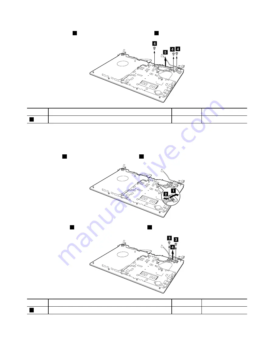
Remove three screws
4
, and then remove the OneLink board
5
.
d
d
d
e
Step
Screw (quantity)
Color
Torque
4
M2 × 3mm, flat-head, nylon-coated (3)
Black
1.85 +/- 0.15kgf-cm
When installing:
Ensure that the OneLink board is firmly attached.
Removal steps of the power board (for the models without dock port)
Open the socket
1
, and then pull out the power cable
2
.
b
a
Remove two screws
3
, and then remove the power board
4
.
c
c
d
Step
Screw (quantity)
Color
Torque
3
M2 × 3mm, flat-head, nylon-coated (2)
Black
1.85 +/- 0.15kgf-cm
When installing:
Ensure that the power board is firmly attached.
80
Hardware Maintenance Manual
Summary of Contents for V510-14IKB
Page 1: ...Hardware Maintenance Manual Lenovo V510 14IKB and Lenovo V510 15IKB ...
Page 4: ...ii Hardware Maintenance Manual ...
Page 6: ...iv Hardware Maintenance Manual ...
Page 11: ...DANGER DANGER DANGER DANGER DANGER Chapter 1 Safety information 5 ...
Page 12: ...6 Hardware Maintenance Manual ...
Page 13: ...PERIGO PERIGO PERIGO PERIGO Chapter 1 Safety information 7 ...
Page 14: ...PERIGO PERIGO PERIGO PERIGO DANGER 8 Hardware Maintenance Manual ...
Page 15: ...DANGER DANGER DANGER DANGER DANGER DANGER Chapter 1 Safety information 9 ...
Page 16: ...DANGER VORSICHT VORSICHT VORSICHT VORSICHT 10 Hardware Maintenance Manual ...
Page 17: ...VORSICHT VORSICHT VORSICHT VORSICHT Chapter 1 Safety information 11 ...
Page 18: ...12 Hardware Maintenance Manual ...
Page 19: ...Chapter 1 Safety information 13 ...
Page 20: ...14 Hardware Maintenance Manual ...
Page 21: ...Chapter 1 Safety information 15 ...
Page 22: ...16 Hardware Maintenance Manual ...
Page 23: ...Chapter 1 Safety information 17 ...
Page 24: ...18 Hardware Maintenance Manual ...
Page 30: ...24 Hardware Maintenance Manual ...
Page 34: ...28 Hardware Maintenance Manual ...
Page 36: ...30 Hardware Maintenance Manual ...
Page 68: ...62 Hardware Maintenance Manual ...
Page 97: ......
Page 98: ......


