


35
Lenovo V340-17IWL
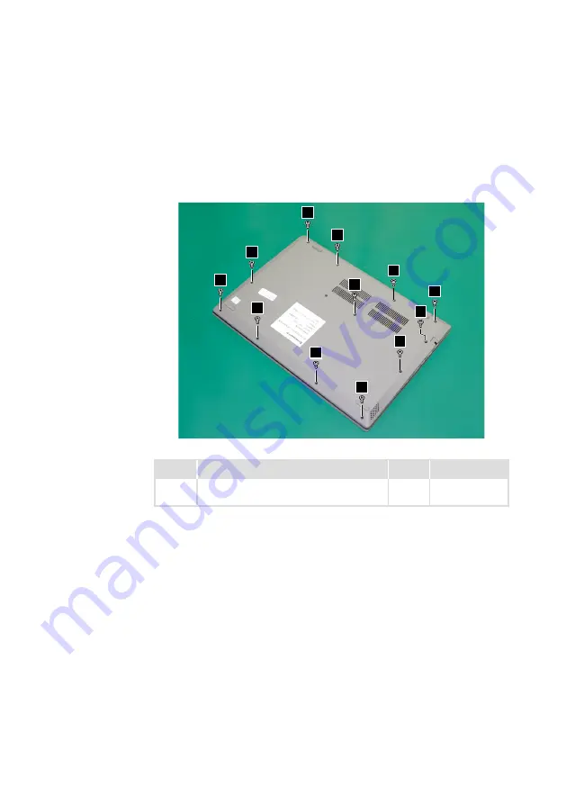
1020 Base cover
For access, remove this FRU:
• “1010 Optical drive” on page 33
Step 1:
Remove the screws
1
.
1
1
1
1
1
1
1
1
1
1
1
1
Figure 3. Remove the screws
Step
Screw (quantity)
Color
Torque
1
M2.5 × 7 mm, Phillips-head, nylok-coated
(12)
Black/
Silver
3.0+/-0.3 kgf/cm