


Installing
memory
Your
computer
has
either
two
or
four
connectors
for
installing
dual
inline
memory
modules
(DIMMs).
Some
computers
have
two
memory
connectors
that
provide
up
to
a
maximum
of
2.0
GB
of
system
memory.
Some
computers
have
four
memory
connectors
that
provide
up
to
a
maximum
of
4.0
GB
of
system
memory.
Your
computer
has
either
double
data
rate
(DDR)
or
double
data
rate
2
(DDR2)
memory.
The
type
of
memory
required
depends
on
the
system
board
that
is
installed
in
your
computer.
v
If
your
computer
has
just
two
memory
connectors,
your
system
board
has
DDR
type
memory.
DDR
memory
modules
are
184-pin,
2.5
V
and
can
be
used
in
any
combination
of
256
MB,
512
MB,
and
1
GB
sizes.
v
If
your
computer
has
four
memory
connectors,
your
system
board
has
DDR2
type
memory.
DDR2
memory
modules
are
240-pin,
1.8
V
and
can
be
used
in
any
combination
of
256
MB,
512
MB,
and
1
GB
sizes.
To
install
a
memory
module:
1.
Remove
the
computer
cover.
See
“Removing
the
cover”
on
page
10.
2.
Access
the
system
board.
See
“Accessing
system
board
components”
on
page
12.
3.
Remove
any
parts
that
might
prevent
access
to
the
memory
connectors.
4.
Locate
the
memory
connectors.
See
“Identifying
parts
on
the
system
board”
on
page
13.
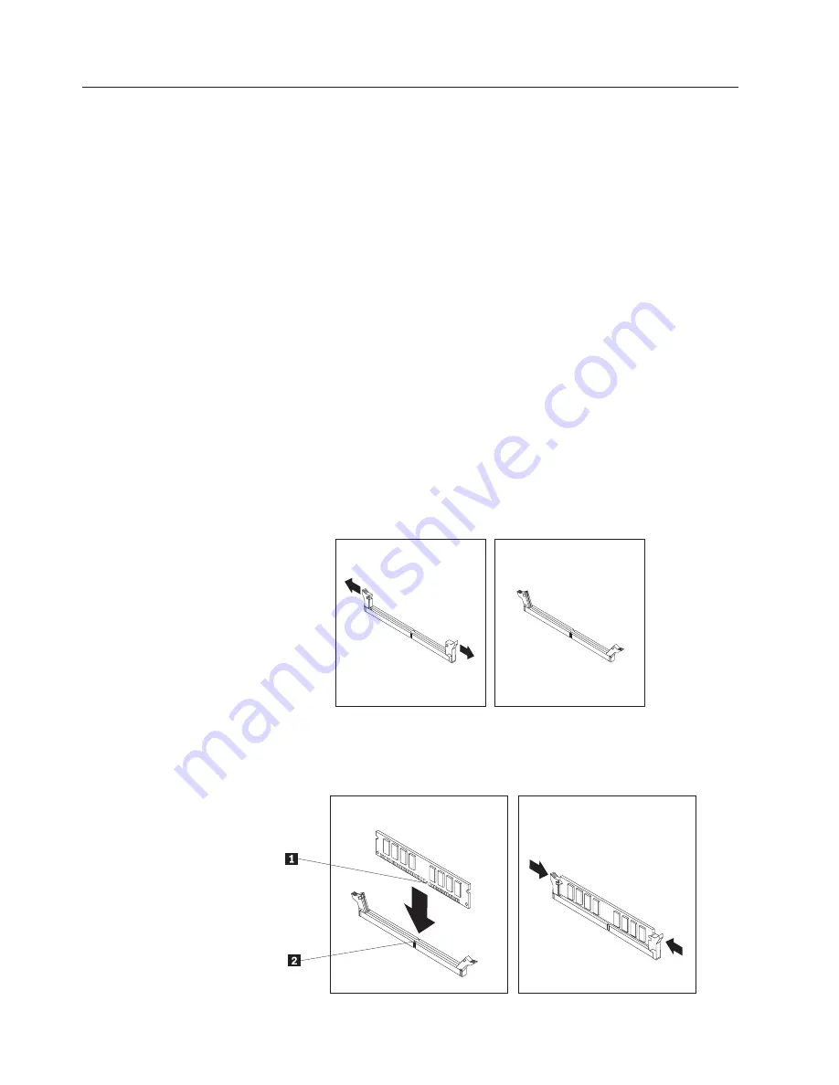
5.
Open
the
retaining
clips.
6.
Position
the
memory
module
over
the
memory
connector.
Make
sure
that
the
notch
1
on
the
memory
module
aligns
correctly
with
the
connector
key
2
on
the
system
board.
Push
the
memory
module
straight
down
into
the
connector
until
the
retaining
clips
close.
18
User
Guide
Summary of Contents for ThinkVision E50
Page 2: ......
Page 6: ...iv User Guide ...
Page 16: ...xiv User Guide ...
Page 40: ...24 User Guide ...
Page 44: ...28 User Guide ...
Page 46: ...30 User Guide ...
Page 56: ...40 User Guide ...
Page 61: ......
Page 62: ...Part Number 41D2699 Printed in USA 1P P N 41D2699 ...