background image


Chapter 3.   

 3-4


Manual image setup

If automatic image setup does not establish the image that you prefer, perform 

manual image setup.(For VGA [analog] only)

Note: 

Have your monitor powered on for about 15 minutes, until the monitor warms 

up.
1. Press  


  to open the OSD menu.

2. Use 


 or 


 to select 


 and press 


  to access.

3. Use   or   to select manual and press 


  to access.

4. Use 


 or 


 to select 

Clock

 and 

Phase

 adjustment. 

Clock

 (pixel frequency) adjusts the number of pixels scanned by one 

horizontal sweep. If the frequency is not correct, the screen shows vertical 

stripes and the picture does not have the correct width.

Phase

 adjusts the phase of the pixel clock signal. With a wrong phase 

adjustment, the picture has horizontal disturbances in light picture.

5. When the image no longer looks distorted, press Enter to save the adjustments of 

Clock 

and 

Phase

.

6. Press 


 to leave the OSD menu.
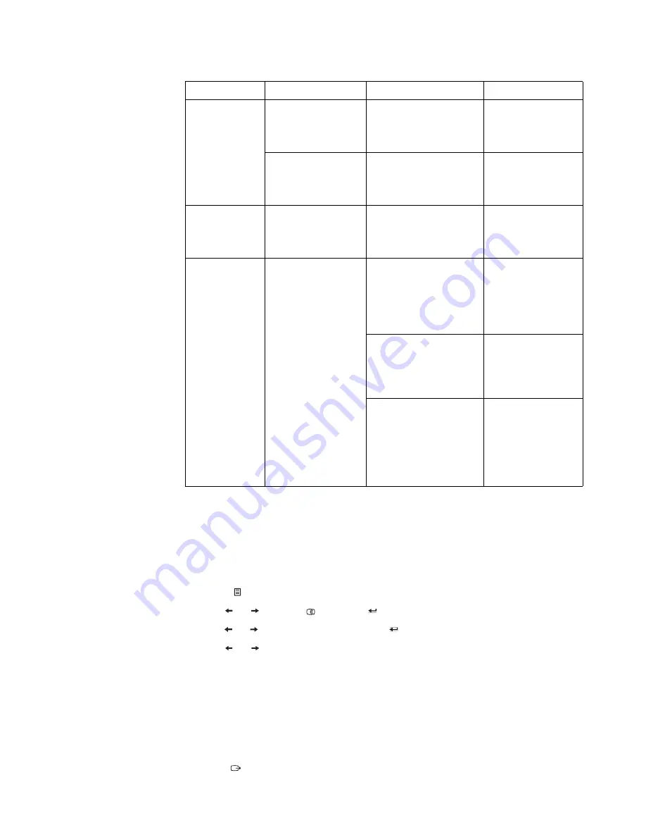
The power 
indicator is 
amber, but there 
is no image.

The video signal cable 
is loose or 
disconnected from the 
system or monitor.

Be sure the video cable is 
connected with the 
system properly.

"Connecting and 
turning on your 
monitor"on page 1-5

The monitor 
brightness and 
contrast are at the 
lowest setting.

Adjust the brightness and 
contrast setting on the 
OSD menu.

"Adjusting your 
monitor image"on 
page 2-3

One or more of 
the pixels appear 
discolored.

This is a characteristic 
of the LCD 
technology and is not 
an LCD defect.

If there are more than five 
pixels missing, contact 
the Support Center.

Appendix A."Service 
and Support"on page 
A-1

Fuzzy lines 
in text or a 
blurry 
image.

Horizontal 
or vertical 
lines 
through the 
image.

Image setup has 
not been 
optimized.

Your  system 
Display 
Properties setting 
have not been 
optimized.

Adjust the resolution 
settings on your system 
to match the native 
resolution for this 
monitor: 1920 x 1080 at 60 
Hz.

"Adjusting your 
monitor image"on 
page 2-3

Perform automatic image 
setup. If automatic image 
setup does not help, 
perform manual image 
setup. 

"Selecting a 
supported display 
mode"on page 2-7

When working in the 
native resolution, you 
may find additional 
improvements by 
adjusting the Dots Per 
Inch (DPI) setting on your 
system.

See the Advanced 
section of your 
system’s display 
properties.

Table 3-2. 

Troubleshooting

Problem

Possible cause

Suggested action

Reference

Summary of Contents for ThinkVision E21-10

Page 1: ...ThinkVision User Guide Machine Types ...

Page 2: ...ommercial items as defined by 48 C F R 2 101 with limited and restricted rights to use reproduction and disclosure LIMITED AND RESTRICTED RIGHTS NOTICE If products data computer software or services are delivered pursuant a General Services Administration GSA contract use reproduction or disclosure is subject to restrictions set forth in Contract No GS 35F 05925 Product numbers 61B9 JAR1 WW ...

Page 3: ...ccess controls 2 3 Using the On Screen Display OSD controls 2 4 Selecting a supported display mode 2 7 Understanding power management 2 8 Caring for your monitor 2 9 Detaching the monitor base and stand 2 9 Wall Mounting Optional 2 9 Chapter 3 Reference information 3 1 Monitor specifications 3 1 Troubleshooting 3 3 Manual image setup 3 4 Manually installing the monitor driver 3 5 Installing the mo...

Page 4: ...iii Safety information General Safety guidelines For tips to help you use your computer safely go to http www lenovo com safety Before installing this product read the Safety Information í í í ...

Page 5: ...ptional Analog Interface Cable Stand Base Detachable Cable Management Notice for use To set up your monitor please see the illustrations below Note Do not touch the monitor within the screen area The screen area is glass and can be damaged by rough handling or excessive pressure 1 Place your monitor with the screen face down on a soft flat surface 2 Align the stand assembly bracket to the monitor ...

Page 6: ... overview This section will provide information on adjusting monitor positions setting user controls and using the cable lock slot Types of adjustments Tilt Please see the illustration below for an example of the tilt range ...

Page 7: ...e front which are used to adjust the display For information on how to use these controls please see Adjusting your monitor image on page 2 3 Cable lock slot Your monitor is equipped with a cable lock slot located on the rear of your monitor in the lower position ...

Page 8: ... Be sure to read the Safety information located on page iii before carrying out this procedure 1 Power off your computer and all attached devices and unplug the computer power cord 2 Connect the cables according to below icon indication 3 Connect one end of the analog signal cable to the monitor D SUB connector and the other end to the computer ...

Page 9: ...monitor then plug the monitor power cord and the computer cord into grounded electrical outlets Note A certified power supply cord has to be used with this equipment The relevant national installation and or equipment regulations shall be considered A certified power supply cord not lighter than ordinary polyvinyl chloride flexible cord according to IEC 60227 designation H05VV F 3G 0 75mm2 or H05V...

Page 10: ...the stand cover 7 Power on the monitor and the computer 8 When you install the monitor driver download the driver that corresponds to your monitor model from the Lenovo website http support lenovo com docs E21_10 Refer to the Manually installing the monitor driver on page 3 5 section to install the driver ...

Page 11: ...Setup key Automatic image setup requires that the monitor is warmed up for at least 15 minutes This is not required for normal opearation Note If automatic image setup does not establish the image that you prefer perform manual image setup See Manual image setup on page 3 4 ...

Page 12: ...he future Your feedback is valuable to us in developing product and services that are important to you as well as in developing better ways to communicate with you Register your option on the following Web site http www lenovo com register Lenovo will send you information and updates on your registered product unless you indicate on the Web site questionnaire that you do not want to receive furthe...

Page 13: ...your computer monitor for comfortable viewing by considering the following items Viewing distance Optimal viewing distances for monitors range from approximately 510 mm to 760 mm 20 in to 30 in and can vary depending on ambient light and time of day You can achieve different viewing distances by repositioning your monitor or by modifying your posture or chair position Use a viewing distance that i...

Page 14: ...mponents and office furniture to best suit your preferences now and as your preferences change over time Minor changes in posture can help avoid discomfort The longer you sit and work with your computer the more important it is to observe your working posture Avoid assuming any one posture for an extended period of time Periodically make minor modifications in your posture to help deter any discom...

Page 15: ...ideo input source DDC CI Press and hold for 10 seconds to enable or disable the DDC CI function Exit Exit and return to previous level 2 Image Setup Activates automatic image adjustment 3 Brightness Direct access to Brightness adjustment Low Blue Light Press and hold for 3 seconds to enable Low Blue Light or disable Low Blue Light 4 Menu To access OSD menu Press to confirm selection Press and hold...

Page 16: ...press to select that function Use or to make adjustments then press to save 3 Press to move backwards through the sub menus and exit from the OSD 4 Press and hold for 10 seconds to lock the OSD This will prevent accidental adjustments to the OSD Press and hold for 10 seconds to unlock the OSD and allow adjustments to the OSD 5 Enables DDC CI by default Use OSD Exit Key Press and hold for 10 second...

Page 17: ...age 3 4 Clock Phase Image Properties Color Adjusts intensity of red green and blue Preset mode Neutral sRGB Reddish Bluish Custom Red Increases or decreases the saturation of Red in the image Green Increases or decreases the saturation of Green in the image Blue Increases or decreases the saturation of Blue in the image Same as Analog Input signal This monitor can accept video signals through two ...

Page 18: ...cted language only affects the language of the OSD It has no effect on any software running on the computer Menu Position Adjusts menu location Default The menu position to the default settings Custom Horizontal Changes the horizontal position of the OSD Vertical Changes the vertical position of the OSD Factory default Reset all settings to the default settings Cancel Reset Accessibility Changes b...

Page 19: ... Flat Panel technology is inherently flicker free Note If your system has previously been used with a CRT monitor and is currently configured to a display mode outside the range of this monitor you may need to reattach the CRT monitor temporarily until you have re configured the system preferably to 1920 x 1080 at 60 Hz which is a common display mode The display modes shown below have been optimiz...

Page 20: ... of each working day or whenever you expect to leave it unused for long periods during the day Table 2 3 Power indicator State Power Indicator Screen Restoring Operation Compliance On Green Normal Standby Suspend Amber Blank Press a key or move the mouse There may be a slight delay before the image reappears Note Standby also occurs if there is no image output to the monitor ENERGY STAR Off Off Bl...

Page 21: ... additives This may harm the coating of the screen area Do Lightly dampen a soft cloth with water and use this to gently wipe the covers and the screen Remove grease or finger marks with a damp cloth and a little mild detergent Detaching the monitor base and stand Step 1 Place the monitor on a soft and flat surface Step 2 Remove the base and stand from the monitor Wall Mounting Optional Refer to t...

Page 22: ... Step 4 Attach the mounting bracket from the VESA compatible wall mounting kit 100mm x100mm distance the type of VESA mounting screw is M4 x 10 mm Step 5 Attach the LCD display to the wall follow the instructions in the wall mounting kit For use only with UL Listed Wall Mount Bracket with minimum weight load 8kg VESA hole ...

Page 23: ... Stand Tilt Range 5 22 VESA mount Supported 100 mm x 100 mm 3 94 in x 3 94 in Image Viewable image size Maximum height Maximum width Pixel pitch 525 mm 20 7 in 257 58 mm 10 14 in 457 92 mm 18 03 in 0 2385 mm 0 01 in Power input Supply voltage Max supply current 100 240VAC 1 5A Power consumption Note Power consumption figures are for the monitor and the power supply combined Normal operation Standb...

Page 24: ...C CI Supported display modes Horizontal frequency Vertical frequency 30 kHz 83 kHz 50 Hz 75 Hz Native Resolution 1920 x 1080 at 60 Hz Temperature Operating Storage Shipping 0 to 45 C 32 to 113 F 20 to 60 C 4 to 140 F 20 to 60 C 4 to 140 F Humidity Operating Storage Shipping 10 to 80 non condensing 5 to 95 non condensing 5 to 95 non condensing Table 3 1 Monitor specifications for type model 61B9 JA...

Page 25: ... cable is not connected with the monitor or system completely Be sure the signal cable is firmly plugged into the system and monitor Connecting and turning on your monitor on page 1 5 The color settings may be incorrect Select another color setting from the OSD menu Adjusting your monitor image on page 2 3 The automatic image setup function was not performed Perform automatic image setup Adjusting...

Page 26: ...with the system properly Connecting and turning on your monitor on page 1 5 The monitor brightness and contrast are at the lowest setting Adjust the brightness and contrast setting on the OSD menu Adjusting your monitor image on page 2 3 One or more of the pixels appear discolored This is a characteristic of the LCD technology and is not an LCD defect If there are more than five pixels missing con...

Page 27: ...Click the Advanced Settings icon 8 Click the Monitor tab 9 Click the Properties button 10 Click the Driver tab 11 Click Update Driver then click Browse the computer to find the driver program 12 Select Pick from the list of device driver program on the computer 13 Click the Hard Disk button By clicking the Browse button browse and point to the following path X Monitor Drivers Windows 7 where X ind...

Page 28: ...e computer to find the driver program 12 Select Pick from the list of device driver program on the computer 13 Click the Hard Disk button By clicking the Browse button browse and point to the following path X Monitor Drivers Windows 10 where X indicates the folder in which the downloaded driver is located such as a desktop 14 Select the lene21 10 inf file and click the Open button Click the OK but...

Page 29: ...image is preventable by utilizing a moving screen saver or power management Physical damage to covers bezel base and cables Scratches or punctures on monitor screens Service parts The following parts are for use by Lenovo service or Lenovo authorized dealers to support the customer warranty Parts are for service use only The table below shows information for model 61B9 JAR1 WW Table 3 3 List of se...

Page 30: ...hone technical support Installation and configuration support through the Customer Support Center will be available until 90 days after the option has been withdrawn from marketing After that time the support is cancelled or made available for a fee at Lenovo s discretion Additional support is also available for a nominal fee Before contacting a Lenovo technical support representative please have ...

Page 31: ... China Macau S A R 0800 807 852 3071 3559 Cantonese English Mandarin Colombia 1 800 912 3021 Spanish Costa Rica 0 800 011 1029 Spanish Croatia 385 1 3033 120 Croatian Cyprus 800 92537 Greek Czech Republic 800 353 637 Czech Denmark Warranty service and support 7010 5150 Danish Dominican Republic 1 866 434 2080 Spanish Ecuador 1 800 426911 OPCION 4 Spanish Egypt Primary 0800 0000 850 Secondary 0800 ...

Page 32: ...sh Israel Givat Shmuel Service Center 972 3 531 3900 Hebrew English Italy Warranty service and support 39 800 820094 Italian Japan 0120 000 817 Japanese English Kazakhstan 77 273 231 427 Standard Charges Apply Russian English Korea 080 513 0880 Collect call 02 3483 2829 Toll Call Korean Latvia 371 6707 360 Latvian Russian English Lithuania 370 5278 6602 Italian Russian English Luxembourg ThinkServ...

Page 33: ...harges Apply Russian Singapore 1 800 415 5529 6818 5315 Standard Charges Apply English Mandarin Bahasa Malaysia Slovakia ThinkStation and ThinkServer 421 2 4954 5555 Slovenia 386 1 2005 60 Slovenian Spain 34 917 147 833 Spanish Sri Lanka 9477 7357 123 Sumathi Information systems English Sweden Warranty service and support 077 117 1040 Swedish Switzerland Warranty service and support 0800 55 54 54 ...

Page 34: ...Appendix A A 5 Uruguay 000 411 005 6649 Spanish Venezuela 0 800 100 2011 Spanish Vietnam 120 11072 Toll Free 84 8 4458 1042 Standard Charges Apply Vietnamese English Country or Region Telephone Number ...

Page 35: ...n new editions of the publication Lenovo may make improvements and or changes in the product s and or the program s described in this publication at any time without notice The products described in this document are not intended for use in implantation or other life support applications where malfunction may result in injury or death to persons The information contained in this document does not ...

Page 36: ...overnment In accordance with the Law for Promotion of Effective Utilization of Resources Lenovo Japan provides through its PC Collecting and Recycling Services for the collecting reuse and recycling of disused computers and monitors For details visit the Lenovo Web site at http www lenovo com recycling japan Pursuant to the Law for Promotion of Effective Utilization of Resources the collecting and...

Page 37: ...o in the United States other countries or both Lenovo The Lenovo logo ThinkCenter ThinkPad ThinkVision Microsoft Windows and Windows NT are trademarks of the Microsoft group of companies Other company product or service names may be trademarks or service marks of others ...

Page 38: ...Appendix B B 4 Power cords and power adapters Use only the power cords and power adapters supplied by the product manufacturer Do not use the ac power cord for other devices ...

Reviews: