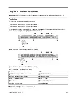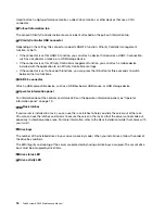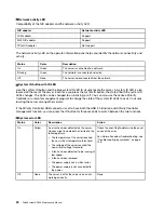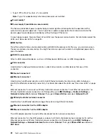
System board components
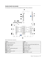
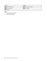
The illustration in this section shows the component locations on the system board.
Figure 10. System board components
Callout
Callout
1
Serial-port-module connector
2
Riser 1 slot
3
LOM adapter connector
4
TCM
1
/TPM
2
connector (for Chinese Mainland only)
5
Front USB connector
6
Front VGA connector
7
DIMM slots
8
Processor 1 socket
9
Operator-information-panel connector
10
System fan connectors
11
Cable retainer
12
Processor 2 socket
13
Backplane power connector
14
CMOS battery
15
Cable retainer
16
Power supply 2 connector
.
27
Summary of Contents for ThinkSystem SR530
Page 1: ...ThinkSystem SR530 Maintenance Manual Machine Types 7X07 and 7X08 ...
Page 8: ...vi ThinkSystem SR530 Maintenance Manual ...
Page 24: ...16 ThinkSystem SR530 Maintenance Manual ...
Page 52: ...44 ThinkSystem SR530 Maintenance Manual ...
Page 72: ...64 ThinkSystem SR530 Maintenance Manual ...
Page 74: ...66 ThinkSystem SR530 Maintenance Manual ...
Page 170: ...162 ThinkSystem SR530 Maintenance Manual ...
Page 174: ...166 ThinkSystem SR530 Maintenance Manual ...
Page 178: ...170 ThinkSystem SR530 Maintenance Manual ...
Page 183: ......
Page 184: ......


