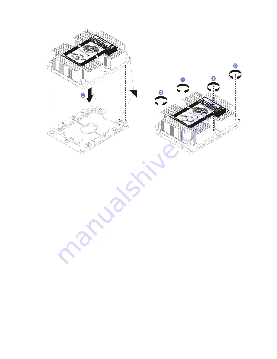
Figure 25. Installing a PHM
a. Align the triangular marks and guide pins on the processor socket with the PHM; then, insert
the PHM into the processor socket.
Attention:
To prevent damage to components, make sure that you follow the indicated
tightening sequence.
b. Fully tighten the Torx T30 captive fasteners
in the installation sequence shown
on the heat-sink
label. Tighten the screws until they stop; then, visually inspect to make sure that there is no
gap between the screw shoulder beneath the heat sink and the processor socket. (For
reference, the torque required for the nuts to fully tighten is 1.4 — 1.6 newton-meters, 12 — 14
inch-pounds).
After installing the PHM option:
• If there are DIMMs to install, install them. See “Install a DIMM” on page 34 for instructions.
Install the interposer card
Use this information to install a interposer card option.
Before you install a interposer card, complete the following steps:
1. Read “Installation Guidelines” on page 26 to ensure that you work safely.
2. Carefully lay the compute node on a flat, static-protective surface, orienting the compute node with the
bezel pointing toward you.
3. Remove the compute node cover (see “Remove the compute node cover” on page 29 for instructions).
To install the interposer card, complete the following steps:
Watch the procedure
. A video of the installation process is available:
• Youtube: https://www.youtube.com/playlist?list=PLYV5R7hVcs-DtV8A4UWy7d3AoFKjCvas3
44
ThinkSystem SN850 Compute Node Setup Guide
Summary of Contents for thinksystem SN850 7X15
Page 1: ...ThinkSystem SN850 Compute Node Setup Guide Machine Type 7X15 ...
Page 4: ...ii ThinkSystem SN850 Compute Node Setup Guide ...
Page 8: ...vi ThinkSystem SN850 Compute Node Setup Guide ...
Page 22: ...14 ThinkSystem SN850 Compute Node Setup Guide ...
Page 76: ...68 ThinkSystem SN850 Compute Node Setup Guide ...
Page 84: ...76 ThinkSystem SN850 Compute Node Setup Guide ...
Page 87: ......
Page 88: ...Part Number SP47A10189 Printed in China 1P P N SP47A10189 1PSP47A10189 ...


