


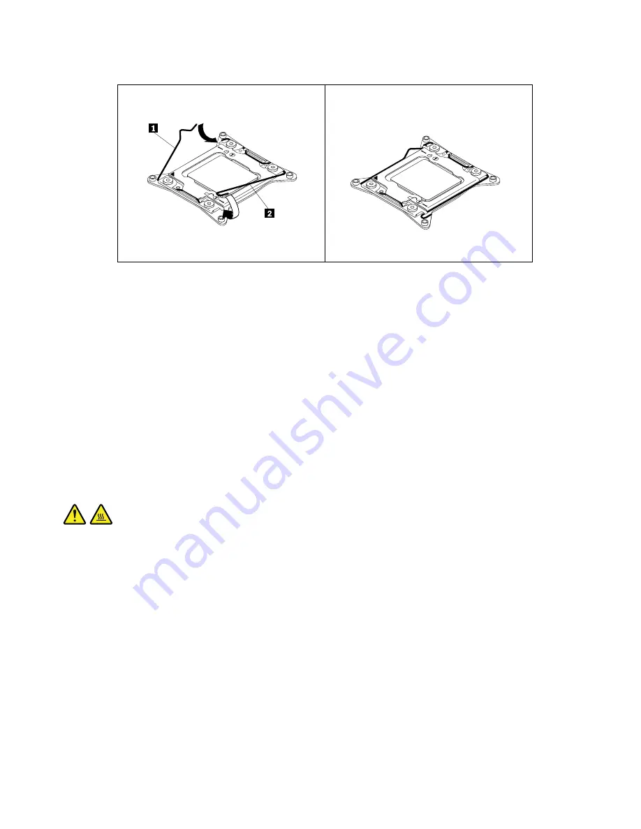
Figure 128. Securing the microprocessor in the socket
15. Reinstall the heat sink and fan assembly. See “Replacing the heat sink and fan assembly” on page 172.
16. If you are instructed to return the old microprocessor, follow all packaging instructions and use any
packaging materials that are supplied to you for shipping.
What to do next:
• To work with another piece of hardware, go to the appropriate section.
• To complete the installation or replacement, go to “Completing the parts replacement” on page 198.
Replacing the system board
Attention:
Do not open your computer or attempt any repair before reading and understanding the Chapter
1 “Read this first: Important safety information” on page 1.
This section provides instructions on how to replace the system board.
CAUTION:
The heat sink and microprocessor might be very hot. Before you open the computer cover, turn off
the computer and wait several minutes until the computer is cool.
Note:
Each computer has a unique Vital Product Data (VPD) code stored in the nonvolatile memory on the
system board. After you replace the system board, the VPD must be updated. To update the VPD, see
“Updating or recovering the BIOS” on page 69.
To replace the system board, do the following:
1. Remove all media from the drives and turn off all attached devices and the computer. Then, disconnect
all power cords from electrical outlets and disconnect all cables that are connected to the computer.
2. Remove the computer cover. See “Removing the computer cover” on page 111.
3. Remove the direct cooling air baffle. See “Removing and reinstalling the direct cooling air baffle” on
4. Lay the computer on its side for easier access to the system board.
5. Remove all PCI or PCI Express cards that are installed. See “Installing or replacing a PCI card” on page
160 and “Installing or replacing a full-length PCI card” on page 165.
6. Remove the optical drive bracket. See “Removing and reinstalling the optical drive bracket” on page 124.
184
ThinkStation P500 and P700 Hardware Maintenance Manual
Summary of Contents for ThinkStation P500
Page 1: ...ThinkStation P500 and P700 Hardware Maintenance Manual Machine Types 30A6 30A7 30A8 and 30A9 ...
Page 14: ...8 ThinkStation P500 and P700 Hardware Maintenance Manual ...
Page 18: ...12 ThinkStation P500 and P700 Hardware Maintenance Manual ...
Page 19: ...1 2 Chapter 1 Read this first Important safety information 13 ...
Page 20: ...1 2 14 ThinkStation P500 and P700 Hardware Maintenance Manual ...
Page 25: ...1 2 Chapter 1 Read this first Important safety information 19 ...
Page 26: ...1 2 20 ThinkStation P500 and P700 Hardware Maintenance Manual ...
Page 29: ...Chapter 1 Read this first Important safety information 23 ...
Page 39: ...Figure 5 Locating major FRUs and CRUs Chapter 2 Product overview 33 ...
Page 52: ...46 ThinkStation P500 and P700 Hardware Maintenance Manual ...
Page 60: ...54 ThinkStation P500 and P700 Hardware Maintenance Manual ...
Page 66: ...60 ThinkStation P500 and P700 Hardware Maintenance Manual ...
Page 100: ...94 ThinkStation P500 and P700 Hardware Maintenance Manual ...
Page 108: ...102 ThinkStation P500 and P700 Hardware Maintenance Manual ...
Page 216: ...210 ThinkStation P500 and P700 Hardware Maintenance Manual ...
Page 220: ...214 ThinkStation P500 and P700 Hardware Maintenance Manual ...
Page 230: ...224 ThinkStation P500 and P700 Hardware Maintenance Manual ...
Page 231: ......
Page 232: ......