


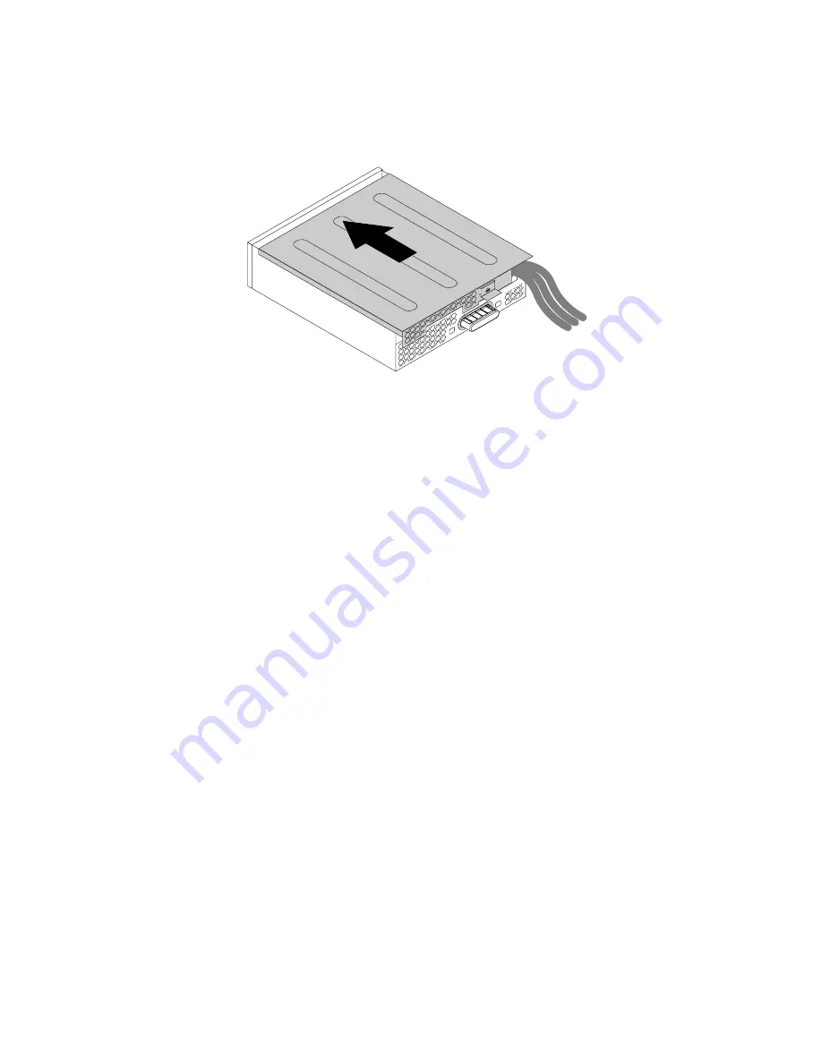
6. Position the flex module cover on the flex module so that the rail guides on the bottom of the flex module
cover engage the rails on the flex module. Then, push the cover to the front of the flex module until
it snaps into position.
Figure 35. Reinstalling the flex module cover
7. Connect the eSATA connector or IEEE 1394 connector cable to the corresponding connector on the
system board. See “Locating parts on the system board” on page 35.
What to do next:
• To work with another piece of hardware, go to the appropriate section.
• To complete the installation or replacement, go to “Completing the parts replacement” on page 198.
Removing and reinstalling the optical drive bracket
Attention:
Do not open your computer or attempt any repair before reading and understanding the Chapter
1 “Read this first: Important safety information” on page 1.
To remove the optical drive bracket, do the following:
1. Remove all media from the drives and turn off all attached devices and the computer. Then, disconnect
all power cords from electrical outlets and disconnect all cables that are connected to the computer.
2. Remove the computer cover. See “Removing the computer cover” on page 111.
3. Remove the direct cooling air baffle. See “Removing and reinstalling the direct cooling air baffle” on
4. Remove the device that is installed in the bracket. See “Installing or replacing a device in the optical
124
ThinkStation P500 and P700 Hardware Maintenance Manual
Summary of Contents for ThinkStation P500
Page 1: ...ThinkStation P500 and P700 Hardware Maintenance Manual Machine Types 30A6 30A7 30A8 and 30A9 ...
Page 14: ...8 ThinkStation P500 and P700 Hardware Maintenance Manual ...
Page 18: ...12 ThinkStation P500 and P700 Hardware Maintenance Manual ...
Page 19: ...1 2 Chapter 1 Read this first Important safety information 13 ...
Page 20: ...1 2 14 ThinkStation P500 and P700 Hardware Maintenance Manual ...
Page 25: ...1 2 Chapter 1 Read this first Important safety information 19 ...
Page 26: ...1 2 20 ThinkStation P500 and P700 Hardware Maintenance Manual ...
Page 29: ...Chapter 1 Read this first Important safety information 23 ...
Page 39: ...Figure 5 Locating major FRUs and CRUs Chapter 2 Product overview 33 ...
Page 52: ...46 ThinkStation P500 and P700 Hardware Maintenance Manual ...
Page 60: ...54 ThinkStation P500 and P700 Hardware Maintenance Manual ...
Page 66: ...60 ThinkStation P500 and P700 Hardware Maintenance Manual ...
Page 100: ...94 ThinkStation P500 and P700 Hardware Maintenance Manual ...
Page 108: ...102 ThinkStation P500 and P700 Hardware Maintenance Manual ...
Page 216: ...210 ThinkStation P500 and P700 Hardware Maintenance Manual ...
Page 220: ...214 ThinkStation P500 and P700 Hardware Maintenance Manual ...
Page 230: ...224 ThinkStation P500 and P700 Hardware Maintenance Manual ...
Page 231: ......
Page 232: ......