


What to do next:
• To work with another piece of hardware, go to the appropriate section.
• To complete the installation or replacement, go to “Completing the parts replacement” on page 198.
Installing or replacing an M.2 solid-state drive on the flex adapter
To install or replace an M.2 solid-state drive on the flex adapter, do the following:
1. Remove all media from the drives and turn off all attached devices and the computer. Then, disconnect
all power cords from electrical outlets and disconnect all cables that are connected to the computer.
2. Remove the computer cover. See “Removing the computer cover” on page 111.
3. Lay the computer on its side for easier access to the flex adapter.
4. Locate and remove the flex adapter with M.2 slots from the system board. See “Installing or replacing a
5. Depending on whether you are installing or replacing an M.2 solid-state drive, do one of the following:
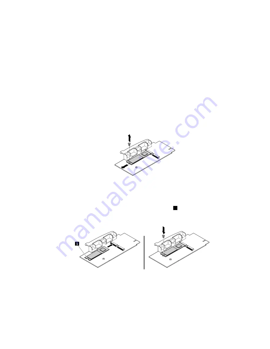
• If you are replacing an M.2 solid-state drive, remove the screw that secures the M.2 solid-state drive.
Then, gently pull the solid-state drive out of the M.2 slot on the flex adapter.
Figure 87. Removing the M.2 solid-state drive
• If you are installing an M.2 solid-state drive, remove the screw corresponding to the M.2 slot where
you want to install the new M.2 solid-state drive.
6. Install the new M.2 solid-state drive into the M.2 slot until the notch
1
is aligned with the corresponding
screw hole in the flex adapter. Then, install the screw to secure the new solid-state drive.
Figure 88. Installing the M.2 solid-state drive
7. Install the flex adapter with the new M.2 solid-state drive into the flex adapter slot on the system board.
See “Installing or replacing a flex adapter” on page 176.
What to do next:
• To work with another piece of hardware, go to the appropriate section.
• To complete the installation or replacement, go to “Completing the parts replacement” on page 198.
Installing or replacing hardware
155
Summary of Contents for ThinkStation P500
Page 1: ...ThinkStation P500 and P700 Hardware Maintenance Manual Machine Types 30A6 30A7 30A8 and 30A9 ...
Page 14: ...8 ThinkStation P500 and P700 Hardware Maintenance Manual ...
Page 18: ...12 ThinkStation P500 and P700 Hardware Maintenance Manual ...
Page 19: ...1 2 Chapter 1 Read this first Important safety information 13 ...
Page 20: ...1 2 14 ThinkStation P500 and P700 Hardware Maintenance Manual ...
Page 25: ...1 2 Chapter 1 Read this first Important safety information 19 ...
Page 26: ...1 2 20 ThinkStation P500 and P700 Hardware Maintenance Manual ...
Page 29: ...Chapter 1 Read this first Important safety information 23 ...
Page 39: ...Figure 5 Locating major FRUs and CRUs Chapter 2 Product overview 33 ...
Page 52: ...46 ThinkStation P500 and P700 Hardware Maintenance Manual ...
Page 60: ...54 ThinkStation P500 and P700 Hardware Maintenance Manual ...
Page 66: ...60 ThinkStation P500 and P700 Hardware Maintenance Manual ...
Page 100: ...94 ThinkStation P500 and P700 Hardware Maintenance Manual ...
Page 108: ...102 ThinkStation P500 and P700 Hardware Maintenance Manual ...
Page 216: ...210 ThinkStation P500 and P700 Hardware Maintenance Manual ...
Page 220: ...214 ThinkStation P500 and P700 Hardware Maintenance Manual ...
Page 230: ...224 ThinkStation P500 and P700 Hardware Maintenance Manual ...
Page 231: ......
Page 232: ......