


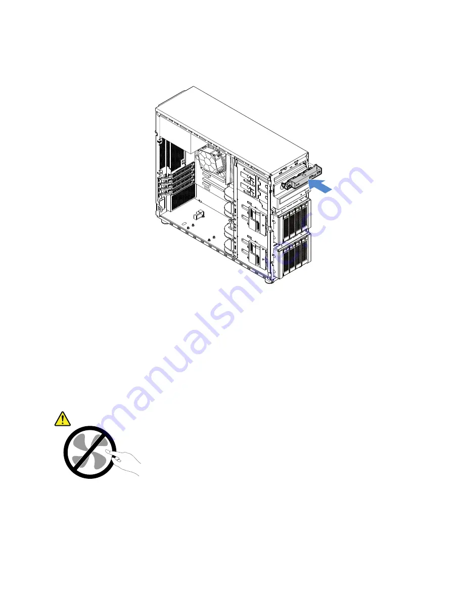
3. Connect cables to the new front panel board assembly and route cables through the corresponding hole
in the chassis. Then, slide the new front panel board assembly into the chassis until it snaps into position.
Figure 69. Installing the front panel board assembly
4. Connect cables to the front panel connector, front USB 3.0 connector, and the HDD LED connectors on
the system board separately. See “System board components” on page 30.
Front system fan
•
“Removing the front system fan 1” on page 93
•
“Installing the front system fan 1” on page 94
CAUTION:
Hazardous moving parts. Keep fingers and other body parts away.
Removing the front system fan 1
To remove the front system fan 1, do the following:
1. Prepare your server and remove the server cover. See “Preparing your server in advance and removing
.
93
Summary of Contents for ThinkServer TS450
Page 14: ...xii ThinkServer TS450 User Guide and Hardware Maintenance Manual ...
Page 18: ...4 ThinkServer TS450 User Guide and Hardware Maintenance Manual ...
Page 48: ...34 ThinkServer TS450 User Guide and Hardware Maintenance Manual ...
Page 64: ...50 ThinkServer TS450 User Guide and Hardware Maintenance Manual ...
Page 142: ...128 ThinkServer TS450 User Guide and Hardware Maintenance Manual ...
Page 152: ...China RoHS 138 ThinkServer TS450 User Guide and Hardware Maintenance Manual ...
Page 154: ...140 ThinkServer TS450 User Guide and Hardware Maintenance Manual ...
Page 165: ......
Page 166: ......


