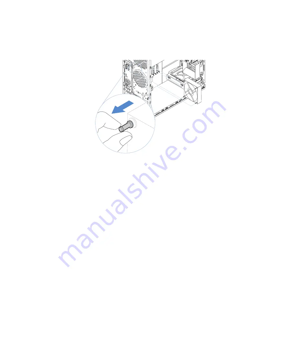
3. Align the rubber mounts of the new rear fan assembly with the corresponding holes in the chassis
and push the rubber mounts through the holes.
4. Carefully pull on the tips of the rubber mounts until the rear fan assembly is secured in place.
Figure 79. Installing the rear fan assembly
5. Connect the rear fan assembly cable to the rear system fan connector on the system board. See
“System board components” on page 20.
Intrusion switch
•
“Removing the intrusion switch” on page 87
•
“Installing the intrusion switch” on page 88
Removing the intrusion switch
To remove the intrusion switch, do the following:
1. Prepare your server. See “Preparing your server and removing the server cover” on page 41.
2. Locate the intrusion switch. See “Server components” on page 17.
3. Disconnect the intrusion switch cable from the system board.
.
87
Summary of Contents for ThinkServer TS150
Page 14: ...xii ThinkServer TS150 User Guide and Hardware Maintenance Manual ...
Page 18: ...4 ThinkServer TS150 User Guide and Hardware Maintenance Manual ...
Page 52: ...38 ThinkServer TS150 User Guide and Hardware Maintenance Manual ...
Page 116: ...102 ThinkServer TS150 User Guide and Hardware Maintenance Manual ...
Page 124: ...110 ThinkServer TS150 User Guide and Hardware Maintenance Manual ...
Page 136: ...122 ThinkServer TS150 User Guide and Hardware Maintenance Manual ...
Page 146: ...132 ThinkServer TS150 User Guide and Hardware Maintenance Manual ...
Page 147: ......
Page 148: ......


