


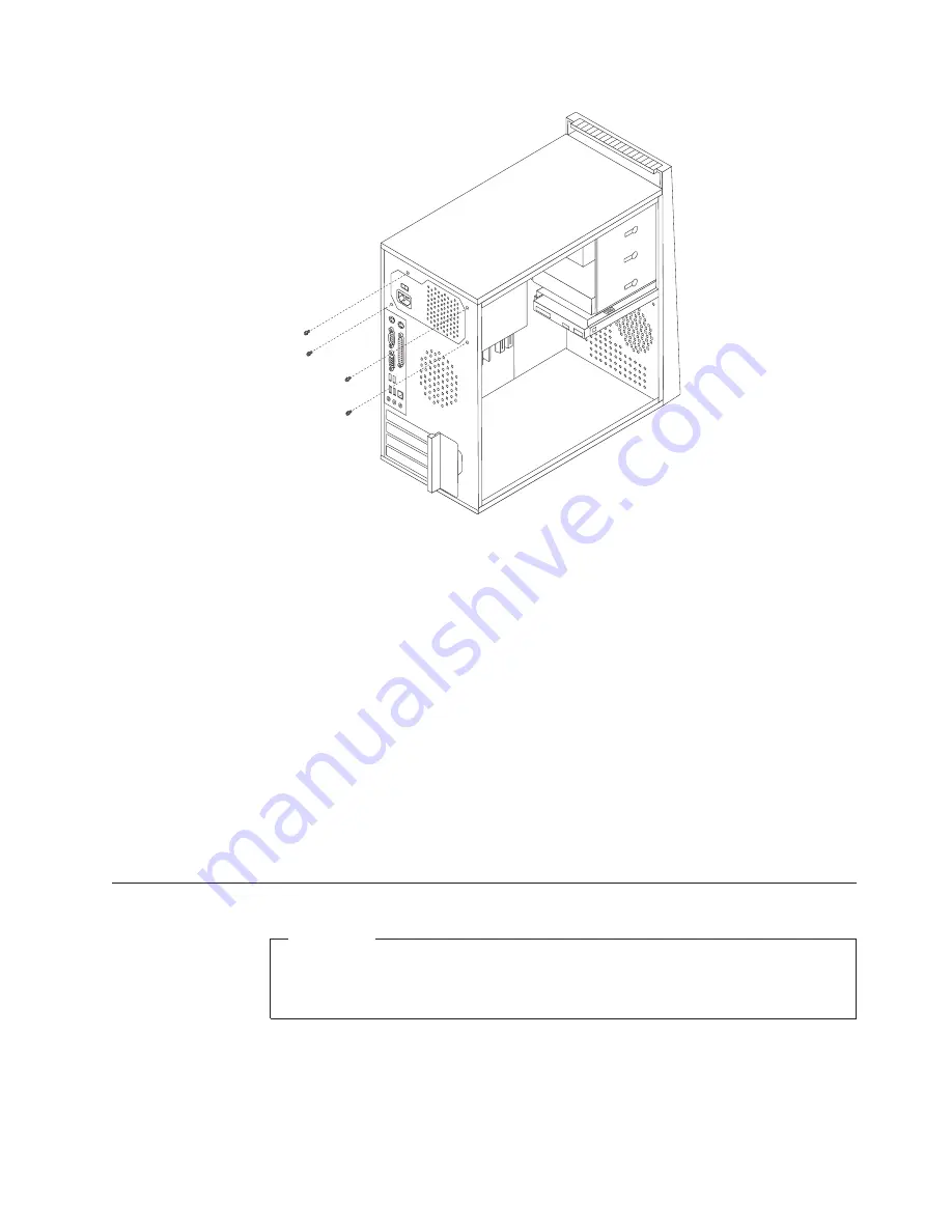
4.
Lift
the
power
supply
out
of
the
chassis.
5.
If
the
power
supply
has
a
voltage-selection
switch,
ensure
that
it
is
set
to
match
the
voltage
available
at
the
electrical
outlet.
v
If
the
voltage
supply
range
in
your
local
country
or
region
is
100-127
V
ac,
set
the
switch
to
115
V.
v
If
the
voltage
supply
range
in
your
local
country
or
region
is
200-240
V
ac,
set
the
switch
to
230
V.
6.
Install
the
new
power
supply
into
the
chassis
so
that
the
screw
holes
in
the
power
supply
align
with
those
in
the
chassis.
7.
Install
the
four
screws
to
secure
the
power
supply.
Note:
Use
only
the
screws
provided
by
Lenovo.
8.
Reconnect
the
power
supply
connectors
to
the
system
board.
See
“Locating
parts
on
the
system
board”
on
page
89.
9.
Reconnect
a
power
supply
connector
to
each
of
the
drives.
10.
Go
to
“Completing
the
FRU
replacement”
on
page
110.
Replacing
the
system
board
Important
The
heat
sink
and
microprocessor
might
be
very
hot.
Make
sure
these
components
are
cool
enough
to
safely
handle
before
continuing
this
procedure.
Note:
When
replacing
the
system
board
you
must
also
order
a
new
retention
module
for
the
new
system
board.
Make
sure
you
have
a
retention
module
for
the
new
system
board
before
continuing
with
this
procedure.
This
procedure
describes
how
to
remove
and
replace
the
system
board.
Chapter
8.
Replacing
FRUs
-
Tower
Computers
91
Summary of Contents for ThinkCentre9126
Page 2: ......
Page 3: ...ThinkCentre Hardware Maintenance Manual ...
Page 17: ...Chapter 2 Safety information 11 ...
Page 18: ...12 Hardware Maintenance Manual ...
Page 19: ... 18 kg 37 lbs 32 kg 70 5 lbs 55 kg 121 2 lbs 1 2 Chapter 2 Safety information 13 ...
Page 23: ...Chapter 2 Safety information 17 ...
Page 24: ...1 2 18 Hardware Maintenance Manual ...
Page 25: ...Chapter 2 Safety information 19 ...
Page 26: ...1 2 20 Hardware Maintenance Manual ...
Page 33: ...Chapter 2 Safety information 27 ...
Page 34: ...28 Hardware Maintenance Manual ...
Page 35: ...1 2 Chapter 2 Safety information 29 ...
Page 39: ...Chapter 2 Safety information 33 ...
Page 40: ...1 2 34 Hardware Maintenance Manual ...
Page 44: ...38 Hardware Maintenance Manual ...
Page 48: ...42 Hardware Maintenance Manual ...
Page 56: ...50 Hardware Maintenance Manual ...
Page 60: ...54 Hardware Maintenance Manual ...
Page 90: ...84 Hardware Maintenance Manual ...
Page 344: ...338 Hardware Maintenance Manual ...
Page 347: ......
Page 348: ...Part Number 43C4864 Printed in USA 1P P N 43C4864 ...


