Lenovo ThinkCentre M910t User Manual And Hardware Maintenance Manual Download Page 53

Replacing FRUs

53

Replacing the front fan

Attention

Do not open your computer or attempt any repairs before reading the 

Important 

Product Information Guide

.

Remove the computer cover.  For details, see 

 Removing the computer cover. 

Remove the front bezel.  For details, see 

 Replacing the front bezel. 

Pivot the drive bay assembly outward.  For details, see 

 Pivoting the drive bay assembly inward and outward. 

Disconnect the front fan cable from the system board.
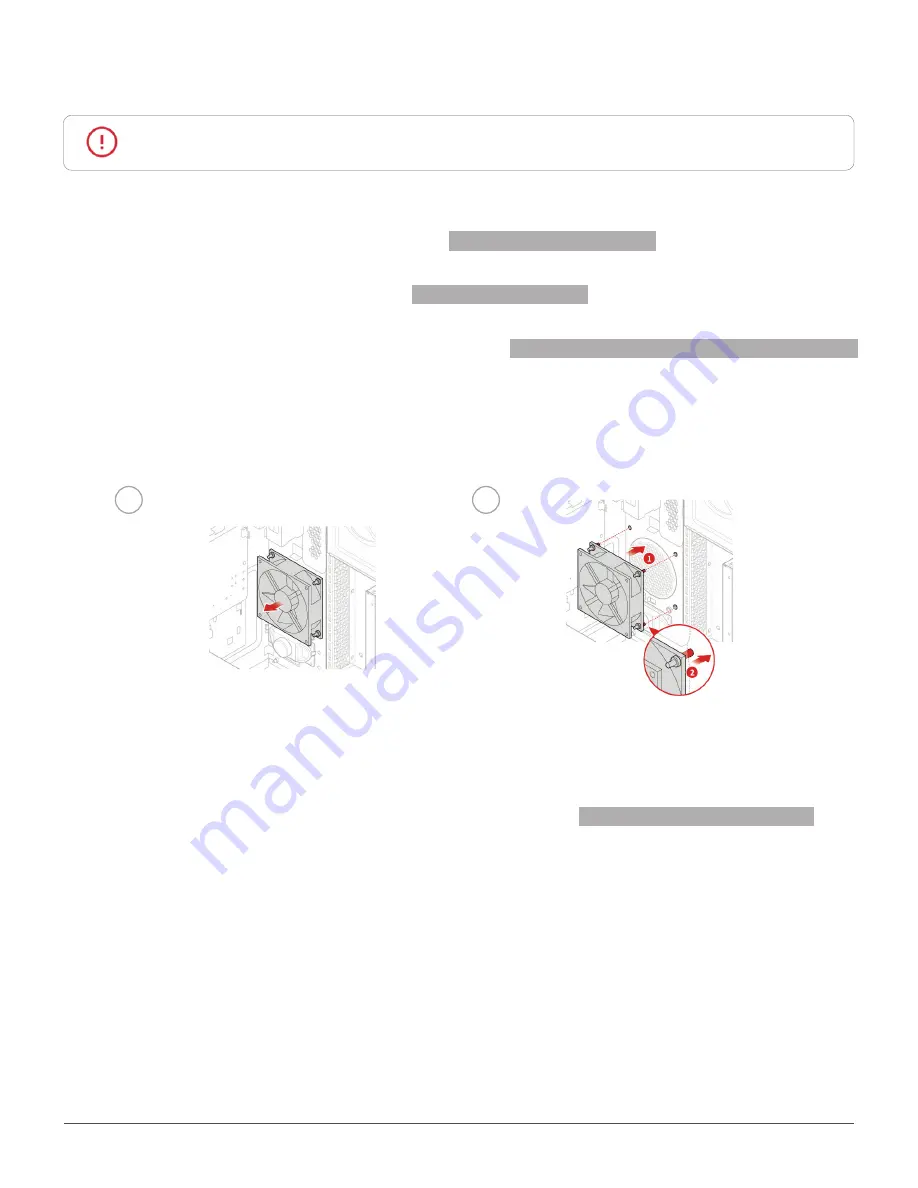
Replace the front fan.

1

2

Connect the new front fan cable to the system board.

Reinstall the removed parts. To complete the replacement, see 

 Completing the parts replacement. 

Summary of Contents for ThinkCentre M910t

Page 1: ...trols provided on your computer Replaceable parts Locations of the replaceable parts on your computer Specifications Specifications of your computer Replacing FRUs Replacing instructions for Field Replaceable Units FRUs for technicians only Computer locks Locking devices for your computer Replacing CRUs Replacing instructions for Customer Replaceable Units CRUs ...

Page 2: ... 31 Replacing the 3 5 inch storage drive in the primary or secondary drive bay 31 Replacing the 3 5 inch storage drive in the front access storage enclosure 33 Replacing the 2 5 inch storage drive in the storage converter 34 Replacing the 2 5 inch storage drive in the tertiary drive bay 34 Replacing the memory module 36 Replacing the coin cell battery 37 Replacing the PCI Express card 38 Replacing...

Page 3: ...nal Used to eject the tray of the optical drive After you insert a disc into the tray press the eject close button to close the tray 4 Optical drive status indicator optional This indicator is on when the optical drive is in use 5 Power button Used to turn on your computer When you cannot shut down the computer from the operating system press and hold the power button for four or more seconds to t...

Page 4: ...ognition software 11 Headphone connector Used to connect headphones to your computer 12 USB 3 0 connectors 4 Used to connect a USB compatible device For optimal data transfer connect a USB 3 0 device to a USB 3 1 or USB 3 0 connector instead of a USB 2 0 connector 13 Illuminated red dot This indicator is on when the computer is on 14 Internal speaker optional Used to listen to the sounds from your...

Page 5: ...e device and the audio line out connector of the computer Note If your computer has both an audio line out connector and a headset or headphone connector always use the headset connector or headphone connector for earphones headphones or a headset The headphone connector does not support headset microphones 3 Microphone connector Used to connect a microphone to your computer when you want to recor...

Page 6: ...ess 11 Power cord connector Used to connect the power cord to your computer for power supply 12 Rear Wi Fi antenna cover Used to protect the rear Wi Fi antenna 13 Serial connector optional Used to connect an external modem a serial printer or other devices that use a serial connector 14 Padlock loop Used to secure a padlock 15 Cable lock slots 2 Used to secure a cable lock 16 PCI Express card area...

Page 7: ...oprocessor fan connector 3 Memory slot DIMM1 4 Memory slot DIMM2 5 Memory slot DIMM3 6 Memory slot DIMM4 7 Power button board connector 8 Internal speaker connector 9 SATA power connector 10 SATA power connector 11 10 pin power connector 12 Auxiliary fan connector 13 SATA 3 0 connector 14 eSATA connector 15 SATA 3 0 connector ...

Page 8: ...tor 22 Front USB 2 0 connector 23 Serial COM2 connector 24 PCI Express card slot physical link width x16 negotiable link width x4 x1 25 PCI Express x1 card slot 26 PCI Express x16 graphics card slot 27 Cover presence switch connector Intrusion switch connector 28 System fan connector 29 Coin cell battery 30 Microprocessor socket 31 PS 2 keyboard and mouse connector ...

Page 9: ...del label identifies the computer When you contact Lenovo for help the machine type and model information helps support technicians to identify the computer and provide faster service The machine type and model label is attached on the side of the computer as shown ...

Page 10: ... card provides an enhanced display experience and extended capabilities Audio features The integrated audio card supports the following Audio line in connector Audio line out connector Headphone connector Internal speaker optional Microphone connector Input Output I O features Audio connectors audio line in connector audio line out connector headphone connector and microphone connector Card reader...

Page 11: ...link width x4 x1 PCI Express x1 card slot PCI Express x16 graphics card slot Storage drive bay Network features Ethernet LAN Wireless LAN optional Bluetooth optional Physical dimensions Width 165 0 mm 6 5 inches Height 410 3 mm 16 2 inches Depth 321 4 mm 12 7 inches Weight without the package Maximum configuration as shipped 10 0 kg 22 1 lb ...

Page 12: ...e a Kensington style cable lock to secure your computer to a desk table or other nonpermanent fixture The cable lock connects to the security lock slot at the rear of your computer Depending on the type selected the cable lock can be operated with a key or combination The cable lock also locks the buttons used to open the computer cover This is the same type of lock used with many notebook compute...

Page 13: ...vice cables to the computer The cable lock connects to the cable lock slots on the rear of the computer To install a cable lock do the following 1 Insert the clip 1 into the cable lock slot 4 2 Pull the cables you want to lock through the dents in the cable lock 3 Press the clip 2 into the cable lock slot 3 until it snaps into position ...

Page 14: ...ugh harmless to you can seriously damage computer components When you handle parts and other computer components take these precautions to avoid static damage Limit your movement Movement can cause static electricity to build up around you Always handle parts and other computer components carefully Handle PCI PCI Express cards memory modules system boards and microprocessors by the edges Never tou...

Page 15: ...rs are responsible for replacing all self service CRUs Optional service CRUs Handling optional service CRUs requires some technical skills and simple tools such as a screwdriver These CRUs are isolated parts within the computer They are usually concealed by an access panel that is secured by more than two screws You must remove the screws and panel to access the specific CRU Optional service CRUs ...

Page 16: ...RU 2 Coin cell battery p 37 4 Memory module p 36 6 M 2 storage drive p 40 8 Optical drive bracket p 29 9 Slim optical drive p 29 10 5 25 inch optical drive p 29 12 Front bezel p 27 19 Inner storage drive bracket p 31 20 Outer storage drive bracket p 31 21 2 5 inch or 3 5 inch storage drive p 31 22 Storage converter p 31 23 Keyboard p 21 24 Mouse p 23 25 Power cord p 25 30 PCI Express card p 38 36 ...

Page 17: ...Replacing hardware 17 Optional service CRU 29 Power supply assembly p 39 34 Wi Fi card shield p 42 35 Wi Fi card p 42 ...

Page 18: ...e p 29 11 Computer handle p 47 13 Front I O bracket p 50 14 Card reader p 49 15 Power button p 48 16 Wi Fi antennas and rear antenna cover p 51 17 Thermal sensor p 55 18 Illuminated red dot p 54 26 Storage drive cable p 31 27 Front fan p 53 28 Internal speaker p 56 31 Chassis 32 Cover presence switch p 57 33 Rear fan p 61 ...

Page 19: ...s self service and optional service To check the locations of CRUs see CRUs and FRUs locations Attention Do not open your computer or attempt any repairs before reading the Important Product Information Guide Before replacing a CRU click the illustration of the part to check the brief procedures Keyboard Computer cover Power cord Drive bay assembly Mouse Front bezel ...

Page 20: ...er supply assembly PCI Express card Wi Fi card Note To replace a component that is not in the list above contact a Lenovo service technician The support phone numbers are available at http www lenovo com support phone Optical drive Memory module Storage drive ...

Page 21: ...reless keyboard is available only on some models Replacing the keyboard 1 Turn off the computer and disconnect all power cords from electrical outlets 2 Disconnect the old keyboard cable from the computer 3 Connect a new keyboard to the appropriate connector on the computer ...

Page 22: ...the package 3 Open the battery compartment cover and install two AAA batteries according to the polarity indicators 4 Remove the USB dongle from the keyboard compartment or from the wireless mouse compartment and connect it to an available USB connector on the computer 5 Close the compartment cover The keyboard is ready for use ...

Page 23: ...disconnect all power cords from electrical outlets 2 Disconnect the old mouse cable from the computer 3 Connect a new mouse to the appropriate connector on the computer Replacing the wireless mouse 1 Disconnect the USB dongle from your computer Then remove your old wireless mouse 2 Remove the new wireless mouse from the package 3 Replace the wireless mouse 1 2 ...

Page 24: ...he flashing amber LED indicates a low battery level Push the power switch to the off position when you are not using the mouse to extend the battery life After disconnecting the USB dongle from your computer store it in the wireless mouse compartment or in the wireless keyboard compartment ...

Page 25: ...er cord 1 Remove any media from the drives and turn off all connected devices and the computer 2 Disconnect all power cords from electrical outlets and disconnect all cables that are connected to the computer 3 Replace the power cord 1 2 ...

Page 26: ...uter and wait several minutes until the computer is cool 1 Remove any media from the drives and turn off all connected devices and the computer 2 Disconnect all power cords from electrical outlets and disconnect all cables that are connected to the computer 3 Unlock any locking device that secures the computer cover 4 Remove the computer cover 5 Complete the replacement For details see Completing ...

Page 27: ...our computer or attempt any repairs before reading the Important Product Information Guide 1 Remove the computer cover For details see Removing the computer cover 2 Replace the front bezel 1 2 3 Complete the replacement For details see Completing the parts replacement ...

Page 28: ... reading the Important Product Information Guide 1 Remove the computer cover For details see Removing the computer cover 2 Remove the front bezel For details see Replacing the front bezel 3 Pivot the drive bay assembly inward and outward 1 2 4 Reinstall the removed parts To complete the replacement see Completing the parts replacement ...

Page 29: ...ding the Important Product Information Guide 1 Remove the computer cover For details see Removing the computer cover 2 Remove the front bezel For details see Replacing the front bezel 3 Disconnect the signal cable and the power cable from the optical drive 4 Replace the optical drive 5 25 inch optical drive 1 2 3 4 ...

Page 30: ...cing CRUs 30 Slim optical drive 1 2 3 4 5 Connect the signal cable and the power cable to the new optical drive 6 Reinstall the removed parts To complete the replacement see Completing the parts replacement ...

Page 31: ...e Removing the computer cover 2 Remove the front bezel For details see Replacing the front bezel 3 If you are replacing the 3 5 inch storage drive in the secondary drive bay pivot the drive bay assembly outward For details see Pivoting the drive bay assembly inward and outward 4 Disconnect the signal cable and the power cable from the 3 5 inch storage drive 5 Refer to the following to replace the ...

Page 32: ...storage drive in the secondary drive bay 1 2 3 4 5 6 6 Connect the signal cable and the power cable to the new 3 5 inch storage drive 7 Reinstall the removed parts To complete the replacement see Completing the parts replacement ...

Page 33: ...Replacing CRUs 33 Replacing the 3 5 inch storage drive in the front access storage enclosure 1 Replace the 3 5 inch storage drive in the front access storage enclosure 1 2 3 4 5 6 ...

Page 34: ...orage drive See Replacing the 3 5 inch storage drive in the primary or secondary drive bay or Replacing the 3 5 inch storage drive in the front access storage enclosure Replacing the 2 5 inch storage drive in the tertiary drive bay 1 Remove the computer cover For details see Removing the computer cover 2 Remove the front bezel For details see Replacing the front bezel 3 Pivot the drive bay assembl...

Page 35: ...placing CRUs 35 1 2 3 4 5 6 6 Connect the signal cable and the power cable to the new 2 5 inch storage drive 7 Reinstall the removed parts To complete the replacement see Completing the parts replacement ...

Page 36: ...ry modules shown in the following figure 1 Remove the computer cover For details see Removing the computer cover 2 Remove the front bezel For details see Replacing the front bezel 3 Pivot the drive bay assembly outward For details see Pivoting the drive bay assembly inward and outward 4 Replace the memory module 1 2 5 Reinstall the removed parts To complete the replacement see Completing the parts...

Page 37: ...ttery lasts forever If the coin cell battery fails the date time and configuration information including passwords are lost An error message is displayed when you turn on the computer To replace the coin cell battery 1 Remove the computer cover For details see Removing the computer cover 2 Remove the front bezel For details see Replacing the front bezel 3 Pivot the drive bay assembly outward For d...

Page 38: ... bezel For details see Replacing the front bezel 3 Pivot the drive bay assembly outward For details see Pivoting the drive bay assembly inward and outward 4 Replace the PCI Express card 1 2 Note If the card is held in place by a retaining latch press the card retaining latch 1 as shown to disengage the latch Grasp the card and gently pull it out of the slot 5 Reinstall the removed parts To complet...

Page 39: ...s are present inside any component that has this label attached There are no serviceable parts inside these components If you suspect a problem with one of these parts contact a service technician 1 Remove the computer cover For details see Removing the computer cover 2 Remove the front bezel For details see Replacing the front bezel 3 Pivot the drive bay assembly outward For details see Pivoting ...

Page 40: ...ide 1 Remove the computer cover For details see Removing the computer cover 2 Remove the front bezel For details see Replacing the front bezel 3 Pivot the drive bay assembly outward For details see Pivoting the drive bay assembly inward and outward 4 Depending on your computer model refer to one of the following to replace the M 2 storage drive Type 1 1 2 3 4 ...

Page 41: ...Replacing CRUs 41 Type 2 1 2 3 4 5 Reinstall the removed parts To complete the replacement see Completing the parts replacement ...

Page 42: ...e 1 Remove the computer cover For details see Removing the computer cover 2 Remove the front bezel For details see Replacing the front bezel 3 Pivot the drive bay assembly outward For details see Pivoting the drive bay assembly inward and outward 4 Depending on your computer model refer to one of the following to replace the Wi Fi card Type 1 1 2 3 4 5 6 ...

Page 43: ...Replacing CRUs 43 Type 2 1 2 3 4 5 6 5 Reinstall the removed parts To complete the replacement see Completing the parts replacement ...

Page 44: ...rectly and that no tools or loose screws are left inside your computer 2 Ensure that the cables are routed correctly before reinstalling the computer cover Keep cables clear of the hinges and sides of the computer chassis to avoid interference when reinstalling the computer cover 3 Reinstall the computer cover 4 Place the computer in an upright position 5 If a locking device is available use it to...

Page 45: ...umber are correct by referring to the website http www lenovo com serviceparts lookup An FRU should not be replaced because of a single unreproducible failure Single failures can occur for a variety of reasons that have nothing to do with a hardware defect such as cosmic radiation electrostatic discharge or software errors Consider replacing an FRU only when a problem recurs If you suspect that an...

Page 46: ...an Front fan Internal speaker Microprocessor Wi Fi antennas Thermal sensor Heat sink and fan assembly System board Note To replace a component that is not in the list above contact a Lenovo service technician The support phone numbers are available at http www lenovo com support phone ...

Page 47: ...reading the Important Product Information Guide 1 Remove the computer cover For details see Removing the computer cover 2 Remove the front bezel For details see Replacing the front bezel 3 Replace computer handle 1 2 4 Reinstall the removed parts To complete the replacement see Completing the parts replacement ...

Page 48: ...ter cover 2 Remove the front bezel For details see Replacing the front bezel 3 Pivot the drive bay assembly outward For details see Pivoting the drive bay assembly inward and outward 4 Disconnect the power button cable from the system board 5 Replace the power button 1 2 6 Connect the new power button cable to the system board 7 Reinstall the removed parts To complete the replacement see Completin...

Page 49: ...puter cover 2 Remove the front bezel For details see Replacing the front bezel 3 Pivot the drive bay assembly outward For details see Pivoting the drive bay assembly inward and outward 4 Disconnect the card reader cable from the card reader 5 Replace the card reader 1 2 6 Connect the new card reader cable to the card reader 7 Reinstall the removed parts To complete the replacement see Completing t...

Page 50: ...reading the Important Product Information Guide 1 Remove the computer cover For details see Removing the computer cover 2 Remove the front bezel For details see Replacing the front bezel 3 Replace front I O bracket 1 2 4 Reinstall the removed parts To complete the replacement see Completing the parts replacement ...

Page 51: ...the computer cover For details see Removing the computer cover 2 Remove the front bezel For details see Replacing the front bezel 3 Pivot the drive bay assembly outward For details see Pivoting the drive bay assembly inward and outward 4 Disconnect the Wi Fi antenna cables from the Wi Fi card 5 Refer to the following to replace the Wi Fi antennas Front Wi Fi antenna 1 2 ...

Page 52: ...Replacing FRUs 52 Rear Wi Fi antenna 1 2 3 4 6 Connect the new Wi Fi antenna cables to the Wi Fi card 7 Reinstall the removed parts To complete the replacement see Completing the parts replacement ...

Page 53: ...mputer cover 2 Remove the front bezel For details see Replacing the front bezel 3 Pivot the drive bay assembly outward For details see Pivoting the drive bay assembly inward and outward 4 Disconnect the front fan cable from the system board 5 Replace the front fan 1 2 6 Connect the new front fan cable to the system board 7 Reinstall the removed parts To complete the replacement see Completing the ...

Page 54: ...er 2 Remove the front bezel For details see Replacing the front bezel 3 Pivot the drive bay assembly outward For details see Pivoting the drive bay assembly inward and outward 4 Disconnect the illuminated red dot cable from the system board 5 Replace the illuminated red dot 1 2 6 Connect the new illuminated red dot cable to the system board 7 Reinstall the removed parts To complete the replacement...

Page 55: ...r cover 2 Remove the front bezel For details see Replacing the front bezel 3 Pivot the drive bay assembly outward For details see Pivoting the drive bay assembly inward and outward 4 Disconnect the thermal sensor cable from the system board 5 Replace the thermal sensor 1 2 6 Connect the new thermal sensor cable to the system board 7 Reinstall the removed parts To complete the replacement see Compl...

Page 56: ...cover 2 Remove the front bezel For details see Replacing the front bezel 3 Pivot the drive bay assembly outward For details see Pivoting the drive bay assembly inward and outward 4 Disconnect the internal speaker cable from the system board 5 Replace the internal speaker 1 2 6 Connect the new internal speaker cable to the system board 7 Reinstall the removed parts To complete the replacement see C...

Page 57: ...ter cover 2 Remove the front bezel For details see Replacing the front bezel 3 Pivot the drive bay assembly outward For details see Pivoting the drive bay assembly inward and outward 4 Disconnect the cover presence switch cable from the system board 5 Replace the cover presence switch 1 2 6 Connect the new cover presence switch cable to the system board 7 Complete the replacement For details see C...

Page 58: ...over 2 Remove the front bezel For details see Replacing the front bezel 3 Pivot the drive bay assembly outward For details see Pivoting the drive bay assembly inward and outward 4 Disconnect the heat sink and fan cable from the system board 5 Replace the heat sink and fan assembly 1 2 6 Connect the new heat sink and fan cable to the system board 7 Reinstall the removed parts To complete the replac...

Page 59: ...l For details see Replacing the front bezel 3 Pivot the drive bay assembly outward For details see Pivoting the drive bay assembly inward and outward 4 Remove the heat sink and fan assembly For details see Replacing the heat sink and fan assembly 5 Disconnect all cables connected to the system board 6 Replace the microprocessor Note Your microprocessor and socket might look different from the one ...

Page 60: ...Replacing FRUs 60 3 4 5 6 7 Reconnect all cables that were disconnected from the system board 8 Reinstall the removed parts To complete the replacement see Completing the parts replacement ...

Page 61: ...ove the computer cover For details see Removing the computer cover 2 Remove the front bezel For details see Replacing the front bezel 3 Pivot the drive bay assembly outward For details see Pivoting the drive bay assembly inward and outward 4 Replace the rear fan 1 2 5 Reinstall the removed parts To complete the replacement see Completing the parts replacement ...

Page 62: ...ssembly outward For details see Pivoting the drive bay assembly inward and outward 6 Remove the memory module For details see Replacing the memory module 7 Remove the heat sink and fan assembly For details see Replacing the heat sink and fan assembly 8 Remove the microprocessor For details see Replacing the microprocessor 9 Remove all PCI Express cards For details see Replacing the PCI Express car...

Page 63: ...board carefully by its edges 14 Route all the cables that you disconnected from the failing system board and then reconnect the cables to the new system board See System board 15 Reinstall the removed parts To complete the replacement see Completing the parts replacement ...

Page 64: ...ANTY OF ANY KIND EITHER EXPRESS OR IMPLIED INCLUDING BUT NOT LIMITED TO THE IMPLIED WARRANTIES OF NON INFRINGEMENT MERCHANTABILITY OR FITNESS FOR A PARTICULAR PURPOSE Some jurisdictions do not allow disclaimer of express or implied warranties in certain transactions therefore this statement may not apply to you This information could include technical inaccuracies or typographical errors Changes a...

Page 65: ...re the result obtained in other operating environments may vary significantly Some measurements may have been made on development level systems and there is no guarantee that these measurements will be the same on generally available systems Furthermore some measurements may have been estimated through extrapolation Actual results may vary Users of this document should verify the applicable data f...

Reviews: