


Installing or replacing a PCI card
Attention
Do not open your computer or attempt any repair before reading and understanding the “Important safety information”
in the
ThinkCentre Safety and Warranty Guide
that came with your computer. To obtain a copy of the
ThinkCentre
Safety and Warranty Guide
, go to:
http://www.lenovo.com/support
This section provides instructions on how to install or replace a PCI card.
Your computer has two standard PCI card slots, one PCI Express x1 card slot, and one PCI Express x16
graphics card slot. See “Locating parts on the system board” on page 99.
To install or replace a PCI card, do the following:
1. Remove all media from the drives and turn off all attached devices and the computer. Then, disconnect
all power cords from electrical outlets and disconnect all cables that are connected to the computer.
2. Remove the computer cover. See “Removing the computer cover” on page 101.
3. Do one of the following:
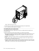
• If you are replacing a PCI card, remove the screw that secures the old PCI card and release the old
PCI card from the PCI card slot. Then, carefully remove the old PCI card from the chassis, as shown
in Removing the PCI card.
Notes:
a. If there are any cables between the PCI card and the system board, note the cable routing and
then disconnect the cables.
b. If the PCI card is secured in place by a retaining latch
1
, press the retaining latch to release the
PCI card from the latch. Then, grasp the PCI card by the edges and carefully pull it out of the
PCI card slot. If necessary, alternate moving each side of the PCI card a small and equal amount
until it is completely removed from the slot.
c. You might need to remove the front bezel and pivot the drive bay assembly upward to avoid
interference with removing the PCI card. See “Removing and reinstalling the front bezel” on page
102 and “Accessing the system board components and drives” on page 103.
Chapter 9
.
Replacing FRUs (Machine Types: 0804, 0809, 0811, 0822, 0825, 0828, 0830, 0833,
0837, 0843, 0845, 0847, and 0849.)
105
Summary of Contents for ThinkCentre M70e
Page 2: ......
Page 8: ...vi ThinkCentre Hardware Maintenance Manual ...
Page 17: ...Chapter 2 Safety information 9 ...
Page 21: ...Chapter 2 Safety information 13 ...
Page 22: ...1 2 14 ThinkCentre Hardware Maintenance Manual ...
Page 23: ...Chapter 2 Safety information 15 ...
Page 29: ...Chapter 2 Safety information 21 ...
Page 33: ...Chapter 2 Safety information 25 ...
Page 40: ...32 ThinkCentre Hardware Maintenance Manual ...
Page 74: ...66 ThinkCentre Hardware Maintenance Manual ...
Page 104: ...96 ThinkCentre Hardware Maintenance Manual ...
Page 402: ...394 ThinkCentre Hardware Maintenance Manual ...
Page 407: ......
Page 408: ...Part Number 71Y8558 Printed in USA 1P P N 71Y8558 71Y8558 ...