background image

Lenovo S435

55

1110 Hinge cover and LCD front bezel

For access, remove these FRUs in order:
• “1010 Battery pack” on page 35
• “1020 Hard disk drive(HDD)/Memory/Mini PCI Express Card slot 

compartment cover” on page 36

• “1030 PCI Express Mini Card for wireless LAN/WAN” on page 37
• “1040 Hard disk drive” on page 39
• “1050 DIMM” on page 41
• “1060 Fan assembly and Heat Sink assembly” on page 42
• “1070 Keyboard” on page 44
• “1080 System board” on page 46
• “1090 LCD unit” on page 50
• “1100 Speakers, base cover, USB board, power assembly and power board” 

on page 52

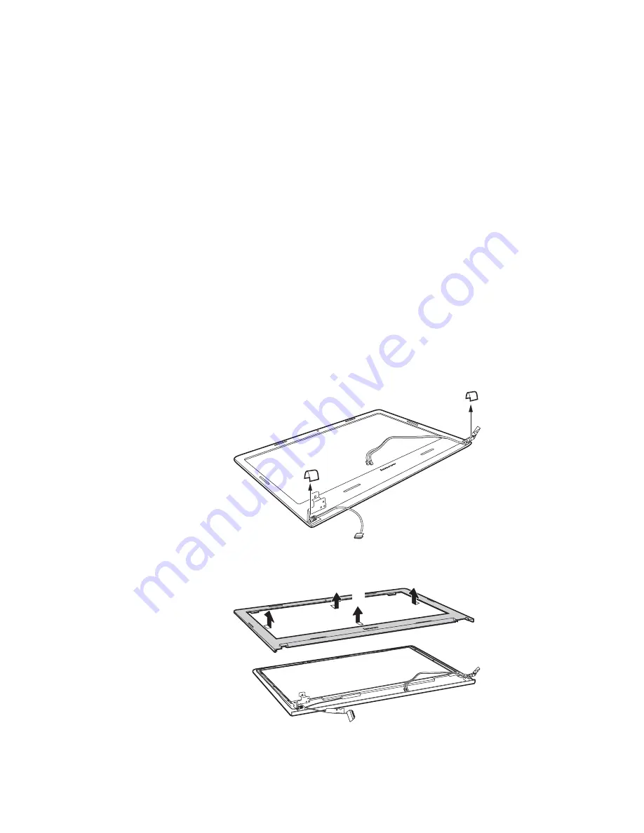
Figure 11. Removal steps of hinge cover and LCD front bezel

Remove hinge covers in the direction shown by arrows 

.

Remove the LCD front bezel in the direction shown by arrows 

.

a

a

a

b

b

b

b

b

Summary of Contents for S435

Page 1: ...Lenovo S435 Hardware Maintenance Manual ...

Page 2: ... developed exclusively at private expense and are sold to governmental entities as commercial items as defined by 48 C F R 2 101 with limited and restricted rights to use reproduction and disclosure LIMITED AND RESTRICTED RIGHTS NOTICE If products data computer software or services are delivered pursuant a General Services Administration GSA contract use reproduction or disclo sure is subject to r...

Page 3: ...rs Recovery Disc one or more discs 23 Supplemental Recovery Disc 23 Passwords 24 Power on password 24 Hard disk password 24 Supervisor password 24 Power management 25 Screen blank state 25 Putting the computer to sleep or shutting it down 25 Lenovo S435 28 Specifications 28 Status indicators 30 Hotkeys 32 FRU replacement notices 33 Screw notices 33 Removing and replacing an FRU 34 1010 Battery pac...

Page 4: ...y information required for servicing computers The product specific section includes service reference and product specific parts information About this manual Important This manual is intended only for trained servicers who are familiar with Lenovo products Use this manual to troubleshoot problems effectively Before servicing a Lenovo product make sure to read all the information under Safety inf...

Page 5: ...ervice a Lenovo computer General safety on page 2 Electrical safety on page 3 Safety inspection guide on page 5 Handling devices that are sensitive to electrostatic discharge on page 6 Grounding requirements on page 6 Safety notices multilingual translations on page 7 Laser compliance statement on page 14 Safety information ...

Page 6: ...l personnel while you are servicing the machine Keep your toolcase away from walk areas so that other people will not trip it over Do not wear loose clothing that can be trapped in the moving parts of the machine Make sure that your sleeves are fastened or rolled up above your elbows If your hair is long fasten it Insert the ends of your necktie or scarf inside clothing or fasten it with the nonco...

Page 7: ...ttention An electrical shock can occur only when there is a complete circuit By observing the above rule you may prevent a current from passing through your body When using testers set the controls correctly and use the approved probe leads and accessories for that tester Stand on suitable rubber mats obtained locally if necessary to insulate you from grounds such as metal floor strips and machine...

Page 8: ... plastic dental mirror The surface is conductive such touching can cause personal injury and machine damage Do not service the following parts with the power on when they are removed from their normal operating places in a machine Power supply units Pumps Blowers and fans Motor generators and similar units This practice ensures correct grounding of the units If an electrical accident occurs Use ca...

Page 9: ...rmine whether there are any potential unsafe conditions use the following checklist at the beginning of every service task Begin the checks with the power off and the power cord disconnected Checklist 1 Check exterior covers for damage loose broken or sharp edges 2 Turn off the computer Disconnect the power cord 3 Check the power cord for a A third wire ground connector in good condition Use a met...

Page 10: ...t is especially useful when handling ESD sensitive devices Select a grounding system such as those listed below to provide protection that meets the specific service requirement Attach the ESD ground clip to any frame ground ground braid or green wire ground When working on a double insulated or battery operated system use an ESD common ground or reference point You can use coax or connector outsi...

Page 11: ... Austausch der Computer wieder angeschlossen wird muß sichergestellt werden daß keine Schrauben Federn oder andere Kleinteile fehlen oder im Gehäuse vergessen wurden Der Computer muß geschüttelt und auf Klappergeräusche geprüft werden Metallteile oder splitter können Kurzschlüsse erzeugen Prima di accendere l elaboratore dopo che é stata effettuata la sostituzione di una FRU accertarsi che tutte l...

Page 12: ...n Sie darf nicht zerlegt wiederaufgeladen kurzgeschlossen oder Feuer oder Wasser ausgesetzt werden Bei der Entsorgung die örtlichen Bestimmungen für Sondermüll beachten Beim Ersetzen der Bereitschafts oder Systembatterie nur Batterien des Typs verwenden der in der Ersatzteilliste aufgeführt ist Der Einsatz falscher Batterien kann zu Entzündung oder Explosion führen Alcune batterie di riserva conte...

Page 13: ...eschlossen oder Feuer oder Wasser ausgesetzt werden Bei der Entsorgung die örtlichen Bestimmungen für Sondermüll beachten Beim Ersetzen der Batterie nur Batterien des Typs verwenden der in der Ersatzteilliste aufgeführt ist Der Einsatz falscher Batterien kann zu Entzündung oder Explosion führen La batteria contiene piccole quantità di nichel Non smontarla gettarla nel fuoco o nell acqua né cortoci...

Page 14: ...s Typs dürfen nicht aufgeladen zerlegt über 100 C erhitzt oder verbrannt werden Auch darf ihr Inhalt nicht mit Wasser in Verbindung gebracht oder der zur richtigen Polung angebrachte Verbindungsstecker entfernt werden Bei der Entsorgung die örtlichen Bestimmungen für Sondermüll beachten Beim Ersetzen der Batterie nur Batterien des Typs verwenden der in der Ersatzteilliste aufgeführt ist Der Einsat...

Page 15: ...irm besteht aus Glas und kann zerbrechen wenn er unsachgemäß behandelt wird oder der Computer auf den Boden fällt Wenn der Bildschirm beschädigt ist und die darin befindliche Flüssigkeit in Kontakt mit Haut und Augen gerät sollten die betroffenen Stellen mindestens 15 Minuten mit Wasser abgespült und bei Beschwerden anschließend ein Arzt aufgesucht werden Nel caso che caso l LCD si dovesse rompere...

Page 16: ...tery can produce enough current to burn personnel or combustible materials Bien que le voltage des batteries principales soit peu élevé le court circuit ou la mise à la masse d une batterie peut produire suffisamment de courant pour brûler des matériaux combustibles ou causer des brûlures corporelles graves Obwohl Hauptbatterien eine niedrige Spannung haben können sie doch bei Kurzschluß oder Erdu...

Page 17: ...et déconnectez tous les cordons d interface Die Stromzufuhr muß abgeschaltet alle Stromkabel aus der Steckdose gezogen der Akku entfernt und alle Verbindungskabel abgenommen sein bevor eine FRU entfernt wird Prima di rimuovere qualsiasi FRU spegnere il sistema scollegare dalle prese elettriche tutti i cavi di alimentazione rimuovere la batteria e poi scollegare i cavi di interconnessione Antes de ...

Page 18: ...ice could result in exposure to hazardous laser radiation There are no serviceable parts inside those drives Do not open Laser compliance statement CAUTION Use of controls or adjustments or performance of procedures other than those specified herein might result in hazardous radiation exposure O uso de controles ajustes ou desempenho de procedimentos diferentes daqueles aqui especificados pode res...

Page 19: ...luz Rayonnement laser si carter ouvert Évitez de fixer le faisceau de le regarder directement avec des instruments optiques ou de vous exposer au rayon Laserstrahlung bei geöffnetem Gerät Nicht direkt oder über optische Instrumente in den Laserstrahl sehen und den Strahlungsbereich meiden Kinyitáskor lézersugár Ne nézzen bele se szabad szemmel se optikai eszközökkel Kerülje a sugárnyalábbal való é...

Page 20: ... in this manual After a system board is replaced ensure that the latest BIOS is loaded to the system board before completing the service action To download software fixes drivers and BIOS follow the steps below 1 Go to http support lenovo com 2 Enter the serial number or select a product or use Lenovo smart downloading 3 Select the BIOS Driver Applications and download 4 Follow the directions on t...

Page 21: ...onfiguration settings using the View Configuration option then when service has been completed verify that those settings remain in effect Strategy for replacing a hard disk drive Always try to run a low level format before replacing a hard disk drive This will cause all customer data on the hard disk to be lost Make sure that the customer has a current backup of the data before performing this ac...

Page 22: ...uppliers to be ready to support Lenovo s requirements and schedule in the EU Products sold in 2005 and 2006 will contain some RoHS compliant FRUs The following statement pertains to these products and any product Lenovo produces containing RoHS compliant FRUs RoHS compliant FRUs have unique FRU part numbers Before or after the RoHS implementation date failed RoHS compliant parts must always be rep...

Page 23: ...ce might have been altered If you select an incorrect drive data or programs might be overwritten Replace an FRU only with another FRU of the correct model When you replace an FRU make sure that the machine model and the FRU part number are correct by referring to the FRU parts list An FRU should not be replaced just because of a single unreproducible failure Single failures can occur for a variet...

Page 24: ...ing to the following list The following are not covered under warranty LCD panel cracked from the application of excessive force or from being dropped Scratched cosmetic parts Distortion deformation or discoloration of the cosmetic parts Plastic parts latches pins or connectors that have been cracked or broken by excessive force Damage caused by liquid spilled into the system Damage caused by the ...

Page 25: ...d of the AC adapter for correct continuity and installation If the computer does not charge during operation go to Checking operational charging To check the AC adapter follow the steps below 1 Unplug the AC adapter cable from the computer 2 Measure the output voltage at the plug of the AC adapter cable See the following figure Note Output voltage for the AC adapter pin No 2 may differ from the on...

Page 26: ...until the Power Meter shows that less than 95 of the total power remains under this condition the battery pack can charge to 100 of its capacity This protects the battery pack from being overcharged or from having a shortened life To check your battery move your cursor to the Power Meter icon in the icon tray of the Windows taskbar and wait for a moment but do not click it and the percentage of ba...

Page 27: ...c This disc contains additional content such as software for specific models and updates to the software that was preloaded on the computer Not all recovery disc sets come with a Supplemental Recovery Disc To restore the computer to the original factory configuration using the recovery disc set do the following 1 Insert the bootable Start Recovery Disc into the optical drive 2 Start the computer W...

Page 28: ...or the system administrator who can use it to get access to the hard disk drive even if the user has changed the user HDP Attention If the user HDP has been forgotten check whether a master HDP has been set If it has it can be used for access to the hard disk drive If no master HDP is available neither Lenovo nor Lenovo authorized service technicians provide any services to reset either the user o...

Page 29: ... you will be away from your computer for only a short time put the computer to sleep When the computer is in sleep mode you can quickly wake it to resume use bypassing the startup process To put the computer to sleep do one of the following Close the display lid Press the power button Open the charms bar and select Settings Power Sleep Note Wait until the power indicator light starts blinking indi...

Page 30: ...f you are not going to use your computer for a long time shut it down To shut down your computer do one of the following Open the charms bar and select Settings Power Shut down Right click the Start button in the lower left corner and select Shut down or sign out Shut down ...

Page 31: ...Related service information 27 On the Start screen click and select Shut down Note This operation depends on your BIOS settings Please refer to the actual product ...

Page 32: ...ist on page 62 The following table lists the specifications of the Lenovo S435 Table 1 Specifications Feature Description Processor See the system properties of your computer you can do this as follows Click Control Panel then click Hardware and Sound click Device Manager under Devices and Printers and double click Processors PCH No Display 16 9 1 366 768 pixels Standard memory DDR3L 1333 MHz 1600...

Page 33: ...iption I O ports HDMI port 1 USB 2 0 2 USB 3 0 1 2 in 1 slot 1 MMC SD Audio Combo audio jack 1 Speaker 2 Built in microphone Video HDMI port 1 AC adapter 40 W or 65 W Pre installed operating system Windows 8 Integrated camera HD 640 480 pixels Battery Lithium ion ...

Page 34: ...Lenovo S435 Hardware Maintenance Manual 30 The system status indicators below show the computer status Status indicators a b ...

Page 35: ...e Solid amber The battery has between 5 and 20 charge Fastblinking amber The battery has less than 5 charge Slow blinking amber The battery is being charged When battery charge reaches 20 the blinking color changes to white Slow blinking white The battery has between 20 and 80 charge and is still charging When the battery reaches 80 charge the light will stop blinking but charging will continue un...

Page 36: ...ion of each hotkey Table 4 Hotkeys Hotkeys Description Mute Unmute Decrease sound volume Increase sound volume Close active window or program Refresh desktop or Web pages Enable Disable the touch pad Enable disable Airplane mode Display all currently active apps Turn on off the backlight of the LCD screen Open the interface for changing display devices Decrease display brightness Increase display ...

Page 37: ...refully for reuse Use a torque screwdriver if you have one Tighten screws as follows Plastic to plastic Turn an additional 90 after the screw head touches the surface of the plastic part Logic card to plastic Turn an additional 180 after the screw head touches the surface of the logic card Torque driver If you have a torque screwdriver refer to the Torque column for each step Make sure that you us...

Page 38: ...re 7 To put the new FRU in place reverse the removal procedures and follow any of the notes that pertain to replacement For information about connecting and arranging internal cables see Locations on page 59 8 When replacing an FRU use the correct screw as shown in the procedures Attention After replacing an FRU do not turn on the computer until you have made sure that all screws springs and other...

Page 39: ...d latch to the unlocked position to eject the battery pack Lift up the inner edge of the battery pack pivoting it on the outer edge Slide the battery pack in the indicated direction to remove it DANGER Only use the battery specified in the parts list for your computer Any other battery could ignite or explode a b c d d c d a b ...

Page 40: ...pen four rubber feet pads with a screw driver in the direction shown by arrows then remove nine screws three screws Open the back cover along the device frame with a flat blade in the direction shown by arrows and then lift the back cover in the direction shown by arrow Step Screw quantity Color Torque M2 5 5 mm flat head nylok coated 9 M2 0 3 mm flat head nylok coated 3 Black Silver 3 0 0 3 kgfcm...

Page 41: ...the USB board cable from the USB board connector in the direction shown by arrow Disconnect the two wireless LAN cables black white and then remove the screw In step unplug the jacks by using the removal tool antenna RF connector P N 08K7159 or pick up the connectors with your fingers and gently unplug them in the direction shown by arrows Notes wireless LAN card has 2 cables in step wireless LAN ...

Page 42: ... with a wireless LAN card that has two antenna connectors plug the black cable 1st MAIN into the jack labeled 1 and the white cable 2nd AUX into jack labeled 2 on the card In models with a wireless LAN card that has three antenna connectors plug the black cable 1st MAIN into the jack labeled 1 the grey cable 3rd into jack labeled 3 and the white cable 2nd AUX into jack labeled 2 on the card e e ...

Page 43: ...e in the direction shown by arrow Take out the hard disk drive secured in a metal frame Step Screw quantity Color Torque M2 3 mm flat head nylok coated 2 Silver 1 85 0 15 kgfcm Attention Do not drop the hard disk drive or apply any physical shock to it The hard disk drive is sensitive to physical shock Improper handling can cause damages and permanent loss of data Before removing the drive suggest...

Page 44: ...f hard disk drive continued Remove four screws and detach the metal frame from the hard disk drive When installing Make sure that the HDD connector is attached firmly Step Screw quantity Color Torque M3 0 3 0 mm flat head nylok coated 4 Silver 3 0 0 3 kgfcm c c c c c c ...

Page 45: ...emoval steps of DIMM Release the two latches on both edges of the socket at the same time in the direction shown by arrows and then unplug the DIMM in the direction shown by arrow When installing Insert the notched end of the DIMM into the socket Push the DIMM firmly and pivot it until it snaps into the place Make sure that it is firmly fixed in the slot and difficult to be moved a b a a b ...

Page 46: ...over on page 36 Figure 6 Removal steps of fan assembly and heat sink assembly Unplug the fan connector in the direction shown by arrow When installing Make sure that the fan connector is attached firmly to the system board Remove six screws and two screws Step Screw quantity Color Torque M2 3 mm flat head nylok coated 6 M2 5 mm flat head nylok coated 2 Silver Black 1 85 0 15 kgfcm 1 85 0 15 kgfcm ...

Page 47: ...novo S435 43 Figure 6 Removal steps of fan assembly and heat sink assembly continued Lift the fan assembly and heat sink assembly in the direction shown by arrow Be careful not to damage the connector d d ...

Page 48: ...drive HDD Memory Mini PCI Express Card slot compartment cover on page 36 1060 Fan assembly and Heat Sink assembly on page 42 Figure 7 Removal steps of keyboard Remove screws Push the back of the keyboard in the direction shown by arrow Step Screw quantity Color Torque M2 0 3 0 mm flat head nylok coated 2 Silver 1 85 0 15 kgfcm a a a a b b ...

Page 49: ... Lift the keyboard a little Pull the keyboard connector slot cover upward as shown by arrow and detach the keyboard cable from the keyboard connector in the direction shown by arrow When installing Make sure that the FPC connector is attached firmly c d e e d c ...

Page 50: ...41 1060 Fan assembly and Heat Sink assembly on page 42 1070 Keyboard on page 44 Important notices for handling the system board When handling the system board bear the following in mind Be careful not to drop the system board on a bench top that has a hard surface such as metal wood or composite Avoid rough handling of any kind In the whole process make sure not to drop or stack the system board I...

Page 51: ... Remove two screws then remove the RJ 45 door Remove five screws Step Screw quantity Color Torque M2 3 mm flat head nylok coated 2 Silver 1 85 0 15 kgfcm Step Screw quantity Color Torque M2 3 mm flat head nylok coated 5 Silver 1 85 0 15 kgfcm a a a a b b b b b b b ...

Page 52: ...LED indicator board connector slot cover upward as shown by arrow and detach the LED indicator board cable from the LED indicator board in the direction shown by arrow Pull the touch pad board and power board connector slot cover upward as shown by arrow and detach the touch pad and power board cable from the touch pad and power board connector in the direction shown by arrow When installing Make ...

Page 53: ...e direction shown by arrow When installing When attaching the system board to the base cover adjust the placement of the USB HDMI RJ 45 ports as shown in and make sure that they are attached to the holes on the base cover as shown Improper placement of those jacks might cause a damage j c b a j ...

Page 54: ...ure 9 Removal steps of LCD unit Remove three screws and the screw When installing Route the antenna cables along the cable guides As you route the cables make sure that they are not subjected to any tension Tension could cause the cables to be damaged by the cable guides or a wire to be broken Make sure that the LCD connector is attached firmly and make sure that you do not pinch the antenna cable...

Page 55: ...Lenovo S435 51 Figure 9 Removal steps of LCD unit continued Detach the LCD unit from the upper case ...

Page 56: ...page 39 1050 DIMM on page 41 1060 Fan assembly and Heat Sink assembly on page 42 1070 Keyboard on page 44 1080 System board on page 46 1090 LCD unit on page 50 Figure 10 Speakers base cover USB board power assembly and power board Remove four screws and then remove the speakers in the direction shown by arrow Remove the power assembly in the direction shown by arrow When installing Make sure that ...

Page 57: ...USB and headphone jacks as shown and make sure that both of the USB and the headphone jacks are attached to the holes on the base cover as shown Improper placement of the jacks might cause a damage Remove the screw to lift the power board in the direction shown by arrow Step Screw quantity Color Torque M2 3 mm flat head nylok coated 2 Silver 1 85 0 15 kgfcm Step Screw quantity Color Torque M2 3 mm...

Page 58: ... the new one Note If the Certificate of Authenticity COA label b is attached to a replaced part return the replaced part to the customer or provide a letter to the customer stating the original label part number serial number and product key The following letter shows the correct location of each label Not all labels are attached on the part you are servicing GML label KR KCC label W L Label for C...

Page 59: ...n page 37 1040 Hard disk drive on page 39 1050 DIMM on page 41 1060 Fan assembly and Heat Sink assembly on page 42 1070 Keyboard on page 44 1080 System board on page 46 1090 LCD unit on page 50 1100 Speakers base cover USB board power assembly and power board on page 52 Figure 11 Removal steps of hinge cover and LCD front bezel Remove hinge covers in the direction shown by arrows Remove the LCD fr...

Page 60: ...AN on page 37 1040 Hard disk drive on page 39 1050 DIMM on page 41 1060 Fan assembly and Heat Sink assembly on page 42 1070 Keyboard on page 44 1080 System board on page 46 1090 LCD unit on page 50 1100 Speakers base cover USB board power assembly and power board on page 52 1110 Hinge cover and LCD front bezel on page 55 Figure 12 LCD panel LCD cable and hinges Remove screws Step Screw quantity Co...

Page 61: ...t the LCD panel in the direction shown by arrow When installing Make sure that the connector is attached firmly Remove four screws and the hinges in the direction shown by arrows Step Screw quantity Color Torque M2 0 x 3 mm flat head nylok coated 4 Black 1 85 0 15 kgfcm b c c b d e d e e d d d a ...

Page 62: ...44 1080 System board on page 46 1090 LCD unit on page 50 1100 Speakers base cover USB board power assembly and power board on page 52 1110 Hinge cover and LCD front bezel on page 55 1120 LCD panel LCD cable and hinges on page 56 Figure 13 Removal steps of integrated camera Note The integrated camera is stuck on the top center of the LCD cover Unplug the connector remove the integrated camera from ...

Page 63: ...Lenovo S435 59 Front view Integrated camera Wireless module antennas Computer display Power button Touch pad Built in microphone System status indicators Locations a b c d e f g a d c b e f g ...

Page 64: ...nance Manual 60 Bottom and Right side view AC power adapter jack USB 2 0 port Combo audio jack Memory card slot Battery latch manual Battery latch spring loaded Battery pack Louvers Speakers a b c d e f g h i b d c a e f g i h b ...

Page 65: ...Lenovo S435 61 Left side view Novo button Fan louvers RJ 45 port HDMI port USB 3 0 port a b c d e a b c e d ...

Page 66: ... following service parts Overall on page 63 LCD FRUs on page 67 Keyboard on page 69 Miscellaneous parts on page 71 AC adapters on page 72 Power cords on page 73 Parts list Notes Each FRU is available for all types or models unless specific types or models are specified ...

Page 67: ...Lenovo S435 63 Overall 1 8 5 3 10 11 12 13 15 b d b c 16 14 4 18 7 9 f 2 a 17 e 6 g ...

Page 68: ...5 MB C S435 NOK UMA E1 6010 10W 5B20H13402 N 5 MB C S435 W8P UMA E1 6010 10W 5B20H13404 N 5 MB C S435 W8S UMA E1 6010 10W 5B20H13407 N 5 MB C S435 NOK DIS A4 6210 15W1G 5B20H13409 N 5 MB C S435 W8P DIS A4 6210 15W1G 5B20H13411 N 5 MB C S435 W8S DIS A4 6210 15W1G 5B20H13413 N 5 MB C S435 NOK DIS A4 6210 15W2G 5B20H13415 N 5 MB C S435 W8P DIS A4 6210 15W2G 5B20H13416 N 5 MB C S435 W8S DIS A4 6210 15...

Page 69: ...5 W8P DIS A6 6310 15W2G 5B20H13390 N 5 MB C S435 W8S DIS A6 6310 15W2G 5B20H13393 N 5 MB C S435 NOK DIS A8 6410 15W1G 5B20H13395 N 5 MB C S435 W8P DIS A8 6410 15W1G 5B20H13400 N 5 MB C S435 W8S DIS A8 6410 15W1G 5B20H13372 N 6 Battery 4Cell 16650 2200mAh 14 8V 32Wh Black Texture S300S400 SY L12S4Z01 14 8V32Wh 4cell bty 121500104 6 Battery 4Cell 16650 2200mAh 14 8V 32Wh Red S300S400SY L12S4Z01 14 8...

Page 70: ...1T HDD 16200658 N 9 Hard disk drive 1TB 5400rpm 7mm Seagate Angsana 7 0mm 2D 6G 1TB 16200660 N 9 Hard disk drive 1TB 5400rpm 7mm WD10SPCX 24HWST0 6G 7mm 1T HDD 16200554 N 9 SSD 500 8G Hybrid 7mm ST500LM000 6G 7mm 500G 8G SSHD 16200391 N 10 VIUS3 Power Board W Cable 90000678 N 11 VIUS3 Fan 90201489 N 12 ZAUSA Thermal DIS 90203323 N 13 ZAUSA Thermal Normal UMA 90203324 N 14 IO Board C S435 5C50H1340...

Page 71: ...Lenovo S435 67 LCD FRUs In Lenovo S435 there are following types of LCDs 14 0 in HD TFT 4 10 9 8 7 5 6 1 3 2 ...

Page 72: ...DP 3 0 AUO B140XTN02 E HW0A HD AG S NB 5D10G95364 N 4 Panel HD AG eDP 3 0 SDC LTN140AT31 401 HD AG S LED1 NB LCD 18200901 N 4 Panel HD AG eDP 3 0 CMI N140BGE EA3 C2 HD AG S LED1 NB LCD 18201578 N 5 VIUS4 Hinge Left 90201591 N 6 VIUS4 Hinge Right 90201592 N 7 EDP Cable C S435 5C10H13410 N 8 Camera 0 3M W O Array MIC BIS BNC1VTTTD 0 3M NB camera 5C20G80277 N 8 Camera C S435 HD 1M 5C20H13418 N 8 Came...

Page 73: ...lian 25213426 Arabic 25213425 German 25213424 French 25213423 Russian 25213422 Traditional Chinese 25213421 Korean 25213420 Canadian English French 25213419 Latin 25213418 Portuguese 25213417 Thai 25213416 Turkish 25213415 Spanish 25213414 Italian 25213413 U K English 25213412 English 25213411 Sunrex Indian 25213470 Czechoslovakian 25213468 Bulgarian 25213469 International English 25213467 Swiss 2...

Page 74: ...glish 25213442 English 25213441 Darfon Indian 25213500 Czechoslovakian 25213498 Bulgarian 25213499 International English 25213497 Swiss 25213496 Slovenian 25213495 Icelandic 25213494 Belgian 25213493 Four Nordic countries 25213492 Hungarian 25213491 Hebrew 25213490 Greek 25213489 Dutch 25213488 Brazilian 25213486 Arabic 25213485 German 25213484 French 25213483 Russian 25213482 Traditional Chinese ...

Page 75: ...7 Rubber Foot Black Front Left d VIUS4 Rubber Foot Red Front Right d ZIUS7 Rubber Foot Black Front Right e VIUS3 TP Board Bracket f VIUS5 TP Board Support Bracket f QIWY4 TP Support Bracket 90201488 90201580 90203037 90201581 90203041 90201582 90203039 90201495 90201813 90200849 N Cable miscellaneous parts g VIUS4 TP Board Cable Note Italicized letters in parentheses are references to the exploded...

Page 76: ...Delta ADP 40NH B 20V2A adapter CCC 36200398 40W Liteon PA 1400 12LC 20V2A adapter CCC 36200405 40W Chicony LN A0403A3C20V2A adapter CCC 36200411 65W Delta ADP 65KH BD 20V3 25A adapter CCC 36200395 65W Liteon PA 1650 56LC20V3 25A adapter CCC 36200402 65W Chicony CPA A065 20V3 25A adapter CCC 36200413 FRU P N CRU ID Screw Pack C S435 5S10H13377 N ...

Page 77: ...5000595 UL LINETEK LP 30B SPT 2 LS15 1m 145000594 UK LINETEK LP 61L H03VV F LS15 1m 145000593 Indian LINETEK PE 361 H05VV F LS15 1m 145000592 Italy LINETEK LS15 H03VV F PE 336 1m 145000591 Korea LINETEK LS15 H05VV F LP E04A 1m 145000590 Australia LINETEK LS15 H03VV F LP 23A 1m 145000589 Taiwan LINETEK LS15 VCTF LP 53 1m 145000588 Japan LINETEK LS15 VCTF LP 54 1m 145000587 Africa LINETEK LS15 H03VV...

Page 78: ...stralia Longwell LP 23A LFC 3R LS 18 1m 145000557 Taiwan Longwell LP 71 VCTF LS 33 1m 145000556 Japan Longwell LP 54 VCTF LS 18 1m 145000555 Africa Longwell LP 39 H03VV F LS 18 1m 145000554 CE Longwell LP 34A H03VV F LS 18 1m 145000553 CCC VOLEX GB10S3 RVV 300 500 VAC5S 1m 145000538 UL Volex US15S3 SPT 2 VAC5S 1m 145000537 Italy VOLEX IT10S3 H03VV F VAC5S 1m 145000535 Denmark VOLEX MP233D H03VV F ...

Page 79: ...ontinued Region P N CRU ID Brazil VOLEX CH10S3 H03VV F VAC5S 1m 145000527 Israel VOLEX SI16S3 H03VV F VAC5S 1m 145000526 CE VOLEX M2511 H03VV F VAC5S 1m 145000525 Switzerland VOLEX MP232 H03VV F VAC5S 1m 145000524 UK VOLEX MP5004 H03VV F VAC5S 1m 145000605 ...

Page 80: ...018 E VCTF 0 75 3C 0021 1m 145500005 Australia lux 0038 H03VV F 0 75 3C 0011 1m 145500006 Taiwan lux 0019 VCTF 0 75 3C 0021 1m 145500007 Korea lux 0033 H03VV F 0 75 3C 0011 1m 145500008 Italy lux 0029 H03VV F 0 75 3C 0011 1m 145500009 Africa lux 0044 H03VV F 0 75 3C 0011 1m 145500010 Brazil lux 0034 H03VV F 0 75 3C 0011 1m 145500011 Israel lux 0041 H03VV F 0 75 3C 0011 1m 145500012 Switzerland lux...

Page 81: ... information could include technical inaccuracies or typographical errors Changes are periodically made to the information herein these changes will be incorporated in new editions of the publication Lenovo may make improvements and or changes in the product s and or the program s described in this publication at any time without notice The products described in this document are not intended for ...

Page 82: ...generally available systems Furthermore some measurements may have been estimated through extrapolation Actual results may vary Users of this document should verify the applicable data for their specific environment The following terms are trademarks or registered trademarks of Lenovo in the United States other countries or both Lenovo OneKey Microsoft and Windows are trademarks of Microsoft Corpo...

Reviews: