background image

Lenovo Moto Z4 

Level 2 – Service and Repair Manual 


Lenovo Confidential Restricted: 

PAGE 158 


Do not share without consent from Lenovo 

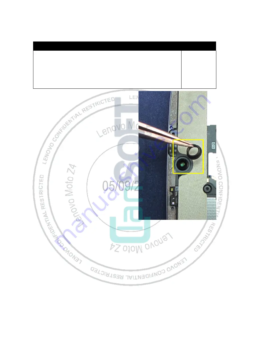
Front-Facing Imager Grommet Assembly  

Description 

Reference # 

Stingray RearCVR FLSHGRY Etching NA 

Stingray RearCVR FLSHGRY Etching VZW 

Stingray RearCVR WHT Etching VZW 

Stingray FRU RearCVR FLSHGRY  

Stingray FRU RearCVR WHITE 

GROM,CUST,STINGRAY,SILC,FOLES_FF CAMR GR 

38 

Use the Tweezers to place the Front-Facing 

Imager Grommet on the Front-Facing Imager as 

shown.  


Summary of Contents for Moto Z4

Page 1: ...Lenovo Confidential Restricted PAGE 1 Do not share without consent from Lenovo Lenovo Moto Z4 Lenovo Moto Z4 Level 2 Service and Repair Manual ...

Page 2: ...Lenovo Moto Z4 Level 2 Service and Repair Manual Lenovo Confidential Restricted PAGE 2 Do not share without consent from Lenovo REVISION HISTORY Revision Date Notes 1 05 09 2019 Initial release ...

Page 3: ...val 16 IMEI Label Removal 17 SIM SD Tray Water Detection Label WDL Inspection 18 Display Removal 19 Display Foil Cushion Removal 29 Proximity Sensor Grommet Removal 31 Side Key Flex Foam Removal 33 WDL Inspection 36 Fingerprint Sensor FPS Removal 37 Battery Cable Cover Removal 39 Foil Cushion Removal 40 Coax Cable Cover Removal 41 Copper Foil Heat Spreader Removal 42 Thermal Pad Removal 43 Audio B...

Page 4: ...mbly 104 Flash Lens Assembly 105 Rear Facing Imager Lens Assembly 107 Flash PCB Assembly 109 Rear Facing Imager Foam Assembly 111 Front Facing Flash Grommet Assembly 112 Vibrator Assembly 114 Main PCB WDL Assembly 117 Headset Jack Grommet Assembly 121 USB Grommet Assembly 122 PCB Coax Cable Assembly 123 Earpiece Speaker Gasket Assembly 125 Front Facing Imager Assembly 126 Thermal Pad Assembly 127 ...

Page 5: ...not share without consent from Lenovo Top Carrier WDL Assembly 152 Proximity Sensor Assembly 153 Top Carrier Tape Assembly 155 Top Carrier Assembly 157 Front Facing Imager Grommet Assembly 158 Battery Graphite Assembly 159 Display Assembly 165 IMEI Label Assembly 170 SIM SD Tray Assembly 171 ...

Page 6: ...ovo Confidential Restricted PAGE 6 Do not share without consent from Lenovo LIST OF TABLES Table 1 External Views Parts List 9 Table 2 Assembly Exploded View Parts List 10 TABLE OF FIGURES Figure 1 External Views 8 459BFigure 2 Assembly Exploded View 10 ...

Page 7: ...t damaged e g scratched dented punctured prior to and throughout assembly Prior to assembly ensure Battery edges and surfaces are not dented or deformed and that fixtures and parts that will contact the Battery are free of foreign material Ensure screws and screwdrivers do not contact the Battery Failure to adhere to Safety Critical Note s may increase risk of rupture burning or failure to functio...

Page 8: ...Lenovo Moto Z4 Level 2 Service and Repair Manual Lenovo Confidential Restricted PAGE 8 Do not share without consent from Lenovo INTRODUCTION External Views Figure 1 External Views ...

Page 9: ...re without consent from Lenovo Table 1 External Views Parts List Reference Description 1 SIM SD Tray 2 Secondary Microphone 3 Top Carrier 4 Speaker Mesh 5 Display 6 Volume Keys 7 Power Key 8 Rear Facing Imager Lens 9 Rear Facing Imager 10 Flash Lens 11 MOD Contacts 12 Primary Microphone 13 USB Port ...

Page 10: ... RearCVR WHT Etching VZW Stingray FRU RearCVR FLSHGRY Stingray FRU RearCVR WHITE YES 6 HSG REAR STINGRAY HSG_INLAY_ FOLES_BLACK LENS OTHR INLAY FOLES BLK AG VZW HSG_INLAY_ FOLES_WHITE AG VZW YES 7 MDL CAMR 0 8um YES 8 MDL CAMR 24M CMOS MIPI O film YES 9 VIBR LIN R4xH3 25 0 205KHz Vibrator R4xH NO 10 Stingray P Sensor OP1 FPCA 15 56x10 44mm NO 11 AU SPKR TBD 8OHM BX 1 5W at 8OHM 800Hz 9 YES 12 HSG ...

Page 11: ...A NO 28 DICUT ADHS ADHS DIECUT_FOLES_MAIN_LENS_A NO 29 DICUT ADHS ADHS DIECUT_FOLES_FLASH_ADHES NO 30 DICUT ADHS PET DIECUT_FOLES_COND_FOAM_OL NO 31 GROM CUST STINGRAY SILC FOLES_TYPE_C_GRO YES 32 GROM CUST STINGRAY SILC FOLES_HEADPHONE_ NO 34 DICUT FOAM GSKT DIECUT_FOLES_FRONT_REC_G NO 35 SHLD CVR STINGRAY MET FOLES_CABLE_FRAME YES 36 SHLD CVR STINGRAY MET FOLES_BTB_CONN_FRA YES 37 IP52_GASKET FO...

Page 12: ...ES THERMAL_ NO DICUT FOAM GSKT DIECUT_FOLES_CABLE_GASKE NO DICUT FOAM MYL DIECUT_FOLES_CONNECTOR_MY NO DICUT FOAM GSKT DIECUT_FOLES_CONDUTIVE_G NO LBL IMEI GHOST NO LBL WATER DETECT 3M 5559 0 127T VZ NO FOLES_OLED_COND_FOAM NO FOLES_SOCKET_COPPER NO FOLES_MODS_MYLAR NO DIECUT_FOLES_JTAG_MYLAR NO DICUT ADHS PET FOLES_LIGHT_GUIDE_FILM NO FOLES_PCB_SUPPORT_FOAM2 NO Refer to this table as a reference ...

Page 13: ...at Spreader Display Film Coax Cable Cover Top Carrier Tape Proximity Sensor Grommet Front Facing Imager Grommet Black Tape Battery Cable Cover Rear Facing Imager Front Housing Main PCB Graphite Heat Spreader Headset Jack Grommet Earpiece Speaker Gasket JTAG Connector Vibrator Foam Small Copper Foil Heat Spreader Front Facing Imager Copper Block Main PCB Support Foam Vibrator PCB Coax Cable USB Gro...

Page 14: ...quired for Disassembly The following tools are required to disassemble the Lenovo Moto Z4 phone Description Part Picture Drawing 7 x 7 Hot Plate SIM SD Tray Removal Tool 4 00 U2 10000 Blackstick T3 Torx Bit Torque Driver Adjustable Shim 4 00 5L 10000 Thin Plastic Spudger 0 00 00 40826 Moto 8th Generation Display Removal Fixture MR M2 003 ...

Page 15: ...cription Part Picture Drawing Moto 7th Generation Display Removal Fixture MR M2 001 Inlay Removal Insert MR M2 001 043 Lens Adhesive Heating Plate 3 00 X1 10000 Metal Shim Tool Optional LCD Screen Opening Pliers Optional IP0092 160315 Tweezers Plastic or Plastic Tipped Tweezers Metal ESD Mat and Wrist Strap Gloves or Finger Collets ...

Page 16: ...from Lenovo SIM SD Tray Removal NOTE The SIM SD Tray can be recovered and reused after removal 1 Insert the SIM SD Tray Removal Tool 4 00 U2 10000 into the SIM SD Tray hole 2 Push the SIM SD Tray Removal Tool into the SIM SD Tray hole until the SIM SD Tray ejects from the phone 3 Remove the SIM SD Tray from the phone ...

Page 17: ...al Lenovo Confidential Restricted PAGE 17 Do not share without consent from Lenovo IMEI Label Removal NOTE Remove the IMEI Label only if necessary After you remove it you cannot reuse it Use the Tweezers to peel the IMEI Label from the SIM SD Tray ...

Page 18: ...tial Restricted PAGE 18 Do not share without consent from Lenovo SIM SD Tray Water Detection Label WDL Inspection NOTE If the WDL is activated the phone s warranty no longer applies Inspect the WDL in the SIM SD Tray Slot as shown Examine it for signs of activation ...

Page 19: ...al if it is undamaged Remove the Display Liner if present NOTE Display Removal Methods A and B have the same preheating steps as shown below 1 Place the Lens Adhesive Heating Plate 3 00 X1 10000 on the Hot Plate 2 Set the Hot Plate to 80 C 176 F CAUTION Do not set the Hot Plate temperature higher than 80 C 176 F Damage to the phone may occur NOTE Preheating with an oven is also acceptable if the o...

Page 20: ...rotective gloves when handling heated phones NOTE Perform the Display removal procedure before the phone starts to cool off 1 Use your fingers to slide the phone into the Moto 8th Generation Display Removal Fixture as shown NOTE Begin this step after removal from the Hot Plate or oven before the phone starts to cool off 2 Slide the phone into the Display Inlay Removal Fixture in the orientation sh...

Page 21: ...are when pressing down on the Display Inlay Removal Fixture handle Damage to the phone may occur 5 20BTurn on the Heat Gun and set the temperature to 80 C 176 F Allow the Heat Gun to warm up for 2 3 minutes 1552B CAUTION 1466BDo not set the Heat Gun temperature higher than 80 C 176 F Damage to the phone may occur 1553B CAUTION 1467BWear protective gloves when handling heated phones 6 Use the Heat ...

Page 22: ...insert any tool into the phone until it has opened Damage to the Top Carrier may occur If damage occurs the Display will need to be replaced 8 Use the Thin Plastic Spudger to cut any remaining adhesive connecting the Display to the Front Housing 9 Use the pointed end of the Blackstick to break the suction on the suction cups attached to the Display You may need to repeat this process on some sucti...

Page 23: ...Lenovo Moto Z4 Level 2 Service and Repair Manual Lenovo Confidential Restricted PAGE 23 Do not share without consent from Lenovo 11 Slide the phone out of the Display Removal Fixture ...

Page 24: ...this step after removal from the Hotplate or oven before the phone starts to cool off 2 Place the phone into the Adjustable Holder of the LCD Screen Opening Pliers IP0092 160315 3 Verify the Display side is up and the base is toward the Plier handles 4 Press the Plier suction cups firmly to attach them to the phone 5 Squeeze the Plier handles until there is enough of a gap between the side of the ...

Page 25: ...t insert the Shim between the Display Lens and the Top Carrier Housing Damage to the Display may occur 8 Slide the Shim Tool around the highlighted perimeter of the Display CAUTION Do not insert thel Shim Tool deeper than 1 mm at the indicated location Deeper insertion may damage the Display Flex NOTE Remove the phone from the Pliers and repeat steps 1 4 to reheat the phone as needed 9 Remove the ...

Page 26: ...lastic Spudger deeper than 1 mm at the indicated location Deeper insertion may damage the Display Flex NOTE Remove the phone from the Pliers and repeat steps 1 4 to reheat the phone as needed 12 102BUse the Thin Plastic Spudger to separate the remaining adhesive from the SIM SD Tray side of the phone 1579B CAUTION 1493BDo not insert the Thin Plastic Spudger deeper than 1 mm Deeper insertion may se...

Page 27: ...play Removal Completion 1 103BLift the left edge of the Display away from the Housing NOTE Do not lift the display excessively to avoid damaging the Display Flex 2 Use the Tweezers to remove the Kapton Tape from the ZIF Connector Door of the Display Flex 3 104BUse the Thin Plastic Spudger to open the Display Flex ZIF Connector Door ...

Page 28: ...dential Restricted PAGE 28 Do not share without consent from Lenovo 4 108BLift the Display away from the Rear Housing NOTE After removing the Display verify that the Top Carrier has not been damaged If the Top Carrier has been damaged the Display must be replaced ...

Page 29: ...al Lenovo Confidential Restricted PAGE 29 Do not share without consent from Lenovo Display Foil Cushion Removal NOTE After you remove the Display Foil Cushion you cannot reuse it Use the Tweezers to remove the Display Foil Cushion from the Display ...

Page 30: ... Repair Manual Lenovo Confidential Restricted PAGE 30 Do not share without consent from Lenovo Display Film Removal NOTE After you remove the Display Film you cannot reuse it Use the Tweezers to remove the Display Film from the Display ...

Page 31: ...ntial Restricted PAGE 31 Do not share without consent from Lenovo Proximity Sensor Grommet Removal NOTE The Proximity Sensor Grommet can be recovered and reused after removal Use the Tweezers to remove the Proximity Sensor Grommet from the pocket in the Top Carrier ...

Page 32: ... Restricted PAGE 32 Do not share without consent from Lenovo Front Facing Imager Grommet Removal NOTE The Front Facing Imager Grommet can be recovered and reused after removal Use the Tweezers to remove the Front Facing Imager Grommet from the pocket in the Rear Housing ...

Page 33: ...onfidential Restricted PAGE 33 Do not share without consent from Lenovo Side Key Flex Foam Removal NOTE After you remove the Side Key Flex Foam you cannot reuse it Use the Tweezers to remove the Side Key Flex Foam from the Side Key Flex in the location shown ...

Page 34: ...anual Lenovo Confidential Restricted PAGE 34 Do not share without consent from Lenovo Black Tape Removal NOTE After you remove the Black Tape you cannot reuse it Use the Tweezers to remove the Black Tape from the front of the Fingerprint Sensor ...

Page 35: ...ite Removal NOTE After you remove the Battery Graphite you cannot reuse it 1 Use the Tweezers to remove the large Battery Graphite as shown 2 Use the Plastic Tweezers to remove the small Battery Graphite as shown CAUTION Use care when removing the small Battery Graphite Sharp objects must not contact the Battery Damage to the phone may occur ...

Page 36: ...ir Manual Lenovo Confidential Restricted PAGE 36 Do not share without consent from Lenovo WDL Inspection NOTE If the WDL is activated the phone s warranty no longer applies Inspect the WDL near the Battery Examine it for signs of activation ...

Page 37: ... The FPS can be recovered and reused after removal 1 Use the Torx Driver and T3 Bit to remove the 2 Machine Screws from the Main PCB in the locations shown NOTE After you remove the Machine Screws you cannot reuse them 2 Use the Thin Plastic Spudger to open the ZIF Connector Door of the FPS Flex 3 Use the Tweezers to remove the FPS Flex from the ZIF Connector Door ...

Page 38: ...Repair Manual Lenovo Confidential Restricted PAGE 38 Do not share without consent from Lenovo 4 Use the Thin Plastic Spudger to disengage the FPS Flex from the Main PCB 5 Use the Tweezers to remove the FPS from the pocket in the Main PCB ...

Page 39: ...Battery Cable Cover Removal NOTE The Battery Cable Cover can be recovered and reused after removal 1 Use the Torx Driver and T3 Bit to remove the Machine Screw from the Main PCB in the location shown NOTE After you remove the Machine Screw you cannot reuse it 2 Use the Tweezers to remove the Battery Cable Cover from the Main PCB ...

Page 40: ...enovo Confidential Restricted PAGE 40 Do not share without consent from Lenovo Foil Cushion Removal NOTE After you remove the Foil Cushions you cannot reuse them Use the Tweezers to remove the 4 Foil Cushions on the right and left sides of the Main PCB ...

Page 41: ...novo Coax Cable Cover Removal NOTE The Coax Cable Cover can be recovered and reused after removal 1 Use the Torx Driver and T3 Bit to remove the Machine Screw from the Main PCB in the location shown NOTE After you remove the Machine Screw you cannot reuse it 2 Use the Tweezers to remove the Coax Cable Cover from the Main PCB ...

Page 42: ...o Confidential Restricted PAGE 42 Do not share without consent from Lenovo Copper Foil Heat Spreader Removal NOTE After you remove the Copper Foil Heat Spreader you cannot reuse it Use the Tweezers to remove the Copper Foil Heat Spreader from the Main PCB ...

Page 43: ...al Lenovo Confidential Restricted PAGE 43 Do not share without consent from Lenovo Thermal Pad Removal NOTE After you remove the Thermal Pads you cannot reuse them Use the Tweezers to remove the Thermal Pads from the Main PCB in the locations shown ...

Page 44: ...rews from the Microphone Bracket in the locations shown NOTE After you remove the Machine Screws you cannot reuse them 2 Use the Tweezers to remove the Microphone Bracket Heat Spreader from the front of the Microphone Bracket NOTE After you remove the Microphone Bracket Heat Spreader you cannot reuse it 3 Use the Thin Plastic Spudger to disengage the snaps that hold the Microphone Bracket to the F...

Page 45: ... can be recovered and reused after removal 1 Use the Torx Driver and T3 Bit to remove the 2 Machine Screws from the Audio Bracket in the locations shown NOTE After you remove the Machine Screws you cannot reuse them 2 Use the Tweezers to remove Headset Jack Heat Spreader from the Headset Jack as shown NOTE After you remove the Headset Jack Heat Spreader you cannot reuse it ...

Page 46: ...o 3 Use the Tweezers to remove the Large Graphite Spreader from the Audio Bracket NOTE After you remove the Large Graphite Heat Spreader you cannot reuse it 4 Use the Thin Plastic Spudger to disengage the snaps that hold the Audio Bracket to the Front Housing 5 Use the Tweezers to remove the Audio Bracket from the Front Housing ...

Page 47: ...ir Manual Lenovo Confidential Restricted PAGE 47 Do not share without consent from Lenovo WDL Inspection NOTE If the WDL is activated the phone s warranty no longer applies Inspect the WDL near the USB Port Examine it for signs of activation ...

Page 48: ...ver and T3 Bit to remove the 7 Machine Screws from the Top Carrier in the locations shown NOTE After you remove the Machine Screws you cannot reuse them 2 Use the flat end of the Blackstick in the location shown to detach the Top Carrier from the Main PCB 3 Use your fingers to lift the Top Carrier from the Main PCB NOTE Use care when lifting the Top Carrier from the Main PCB to avoid damaging the ...

Page 49: ... Confidential Restricted PAGE 49 Do not share without consent from Lenovo 4 Use the Thin Plastic Spudger to disengage the Proximity Sensor Flex BtB Connector from the Main PCB 5 Use your fingers to remove the Top Carrier from the pocket in the Front Housing ...

Page 50: ...al Lenovo Confidential Restricted PAGE 50 Do not share without consent from Lenovo Top Carrier Tape Removal NOTE After you remove the Top Carrier Tape you cannot reuse it Use the Tweezers to remove the Top Carrier Tape from the Top Carrier as shown ...

Page 51: ...re without consent from Lenovo Proximity Sensor Removal NOTE After you remove the Proximity Sensor you cannot reuse it 1 Use the Thin Plastic Spudger to loosen the adhesive holding the Proximity Sensor to the Top Carrier as shown 2 Use the Tweezers to remove the Proximity Sensor from the Top Carrier ...

Page 52: ...al 1 Use the Thin Plastic Spudger to disengage the Rear Facing Imager BtB Connector from the Main PCB 2 Use the Thin Plastic Spudger to gently disengage the Rear Facing Imager from the Main PCB in the location shown CAUTION Use care when disengaging the Rear Facing Imager from the Main PCB Damage to the phone may occur 3 Use the flat end of the Blackstick to disengage the Rear Facing Imager from t...

Page 53: ...o Moto Z4 Level 2 Service and Repair Manual Lenovo Confidential Restricted PAGE 53 Do not share without consent from Lenovo 4 Use the Tweezers to remove the Rear Facing Imager from the pocket in the Main PCB ...

Page 54: ... Main PCB Removal NOTE The Main PCB can be recovered and reused after removal 1 Use the Torx Driver and T3 Bit to remove the 2 Machine Screws from the Main PCB in the locations shown NOTE After you remove the Machine Screws you cannot reuse them 2 Use the Thin Plastic Spudger to open the ZIF Connector Door for the Side Key Flex ...

Page 55: ...ovo Confidential Restricted PAGE 55 Do not share without consent from Lenovo 3 Use the Tweezers to disengage the Side Key Flex from the ZIF Connector on the Main PCB 4 Use the Thin Plastic Spudger to disconnect the Battery BTB Connector from the Main PCB ...

Page 56: ...re without consent from Lenovo 5 Use the Plastic Tweezers to disengage the top Coax Cable BtB Connector from the Main PCB 6 Use the Plastic Tweezers to disengage the bottom Coax Cable BtB Connector from the Main PCB 7 Use your fingers to carefully lift the Main PCB free of the Front Housing as shown ...

Page 57: ... Lenovo Confidential Restricted PAGE 57 Do not share without consent from Lenovo Main PCB Support Foam Removal NOTE After you remove the Main PCB Support Foam you cannot reuse it Use the Tweezers to remove the Main PCB Support Foam from the Main PCB ...

Page 58: ...Lenovo Confidential Restricted PAGE 58 Do not share without consent from Lenovo Joint Test Action Group JTAG Connector Removal NOTE After you remove the JTAG Connector you cannot reuse it Use the Tweezers to remove the JTAG Connector from the Main PCB ...

Page 59: ...out consent from Lenovo Front Facing Imager Removal NOTE The Front Facing Imager can be recovered and reused after removal 1 Use the Thin Plastic Spudger to disengage the Front Facing Imager BtB Connector from the Main PCB 2 Use the Tweezers to remove the Front Facing Imager from the pocket in the Main PCB ...

Page 60: ...novo Confidential Restricted PAGE 60 Do not share without consent from Lenovo Earpiece Speaker Gasket Removal NOTE After you remove the Earpiece Speaker Gasket you cannot reuse it Use the Tweezers to remove the Earpiece Speaker Gasket from the Main PCB ...

Page 61: ...ut consent from Lenovo PCB Coax Cable Removal NOTE The PBC Coax Cable can be recovered and reused after removal 1 Use the Plastic Tweezers to disengage the Main PCB Coax Cable from the clips on the Main PCB in the locations shown 2 Use the Plastic Tweezers to remove the Main PCB Coax Cable from the Main PCB ...

Page 62: ...novo Confidential Restricted PAGE 62 Do not share without consent from Lenovo Headset Jack Grommet Removal NOTE The Headset Jack Grommet can be recovered and reused after removal Use the Tweezers to remove the Headset Jack Grommet from the Headset Jack ...

Page 63: ...Repair Manual Lenovo Confidential Restricted PAGE 63 Do not share without consent from Lenovo USB Grommet Removal NOTE The USB Grommet can be recovered and reused after removal Use the Tweezers to remove the USB Grommet from the USB Port ...

Page 64: ...estricted PAGE 64 Do not share without consent from Lenovo Main PCB Graphite Heat Spreader Removal NOTE After you remove the Main PCB Graphite Heat Spreader you cannot reuse it Use the Tweezers to remove the Main PCB Graphite Heat Spreader from the shield of the Main PCB ...

Page 65: ...estricted PAGE 65 Do not share without consent from Lenovo Small Copper Foil Heat Spreader Removal NOTE After you remove the Small Copper Foil Heat Spreader you cannot reuse it Use the Tweezers to remove the Small Copper Foil Heat Spreader from the shield of the Main PCB ...

Page 66: ...ual Lenovo Confidential Restricted PAGE 66 Do not share without consent from Lenovo Copper Block Removal NOTE After you remove the Copper Block you cannot reuse it Use the pointed end of the Blackstick to remove the Copper Block from the Main PCB ...

Page 67: ... Manual Lenovo Confidential Restricted PAGE 67 Do not share without consent from Lenovo Vibrator Foam Removal NOTE After you remove the Vibrator Foam you cannot reuse it Use the Tweezers to remove the Vibrator Foam from the top of the Vibrator ...

Page 68: ...ricted PAGE 68 Do not share without consent from Lenovo Vibrator Removal NOTE After you remove the Vibrator you cannot reuse it 1 Use the flat end of the Blackstick to pry the Vibrator Flex from the Front Housing 2 Use the Tweezers to lift the Vibrator from the Front Housing ...

Page 69: ...idential Restricted PAGE 69 Do not share without consent from Lenovo Rear Facing Imager Foam Removal NOTE After you remove the Rear Facing Imager Foam you cannot reuse it Use the Tweezers to remove the Rear Facing Imager Foam from the pocket in the Front Housing ...

Page 70: ... and must be scrapped Ensure Battery and its insulation are not damaged e g scratched dented punctured prior to and throughout assembly Prior to assembly ensure Battery edges and surfaces are not dented or deformed and that fixtures and parts that will contact the Battery are free of foreign material Ensure screws and screwdrivers do not contact the Battery 1 Use the Tweezers to remove the Kapton ...

Page 71: ...ry Adhesive to warm up 5 Remove the phone from the Heating Plate or the oven NOTE Wear protective gloves when handling heated phones NOTE Perform the Battery removal procedure before the phone starts to cool off 6 Use the Thin Plastic Spudger to loosen the adhesive holding the Battery to the Rear Housing as shown Slide the Thin Plastic Spudger across both sides of the Battery 7 Use your fingers to...

Page 72: ...are without consent from Lenovo Battery Pad Removal NOTE After you remove the Battery Pad you cannot reuse it Use the Plastic Tweezers to remove the Battery Pad from the bottom of the Battery CAUTION Use care when removing the Battery Pad from the Battery Do not puncture bend or damage the Battery ...

Page 73: ... share without consent from Lenovo Coax Cable Removal NOTE The Coax Cable can be recovered and reused after removal 1 Use the Tweezers to remove the Coax Cable Tape from the front of the Coax Cable 2 Use the Plastic Tweezers to remove the Coax Cable from the recess in the Front Housing as shown ...

Page 74: ...ial Restricted PAGE 74 Do not share without consent from Lenovo Front Facing Flash Grommet Removal NOTE After you remove the Front Facing Flash Grommet you cannot reuse it Use the Tweezers to remove the Front Facing Flash Grommet from the pocket in the Front Housing ...

Page 75: ...dential Restricted PAGE 75 Do not share without consent from Lenovo Front Housing Foam Grommet Removal NOTE The Front Housing Foam Grommets can be recovered and reused after removal Use the Tweezers to remove the Front Housing Foam Grommets from the FrontHousing ...

Page 76: ... 00 X1 10000 on the Hot Plate 2 Set the Hot Plate to 80 C 176 F CAUTION Do not set the Hot Plate temperature higher than 80 C 176 F Damage to the phone may occur CAUTION Use protective gloves when handling heated phones NOTE Preheating with an oven is also acceptable if the oven is set to the same temperature 3 Place the Rear Housing on the Heating Plate lens side down 4 Heat the phone for 10 minu...

Page 77: ... Service and Repair Manual Lenovo Confidential Restricted PAGE 77 Do not share without consent from Lenovo 5 Use the pointed end of the Blackstick to disengage the Rear Facing Imager Lens from the pocket in the Rear Housing ...

Page 78: ...the Hot Plate 2 Set the Hot Plate to 80 C 176 F CAUTION Do not set the Hot Plate temperature higher than 80 C 176 F Damage to the phone may occur CAUTION Use protective gloves when handling heated phones NOTE Preheating with an oven is also acceptable if the oven is set to the same temperature 3 Place the Rear Housing on the Heating Plate lens side down 4 Heat the phone for 10 minutes NOTE Perform...

Page 79: ...Moto Z4 Level 2 Service and Repair Manual Lenovo Confidential Restricted PAGE 79 Do not share without consent from Lenovo 5 Use the flat end of the Blackstick to disengage the Flash Lens from the Rear Housing ...

Page 80: ...Plate 2 Set the Hot Plate to 80 C 176 F CAUTION Do not set the Hot Plate temperature higher than 80 C 176 F Damage to the phone may occur CAUTION Use protective gloves when handling heated phones NOTE Preheating with an oven is also acceptable if the oven is set to the same temperature 3 Place the Rear Housing on the Heating Plate lens side down 4 Heat the phone for 10 minutes NOTE Perform the Fla...

Page 81: ...nual Lenovo Confidential Restricted PAGE 81 Do not share without consent from Lenovo 5 Use the flat end of the Blackstick to disengage the Flash PCB from the Rear Housing 6 Use the Tweezers to remove the Flash PCB from the Front Housing as shown ...

Page 82: ... Plate 2 Set the Hot Plate to 80 C 176 F CAUTION Do not set the Hot Plate temperature higher than 80 C 176 F Damage to the phone may occur CAUTION Use protective gloves when handling heated phones NOTE Preheating with an oven is also acceptable if the oven is set to the same temperature 3 Place the Rear Housing on the Heating Plate lens side down 4 Heat the phone for 10 minutes NOTE Perform the Re...

Page 83: ...play Removal Insert in place if present Remove the Insert 7 Orient the Rear Inlay Removal Insert in relation to the Display Inlay Removal Fixture as shown Place the Insert in the Display Inlay Removal Fixture 8 Use the 3 mm Allen Wrench on the 2 center screws to tighten the Rear Inlay Removal Insert into position 9 Follow preheating steps described on page 19 NOTE Begin this step after removal fro...

Page 84: ... Use care when pressing down on the Display Inlay Removal Fixture handle Damage to the phone may occur 12 20BTurn on the Heat Gun and set the temperature to 80 C 176 F Allow the Heat Gun to warm up for 2 3 minutes 1552B CAUTION 1466BDo not set the Heat Gun temperature higher than 80 C 176 F Damage to the phone may occur 1553B CAUTION 1467BWear protective gloves when handling heated phones 13 Use t...

Page 85: ...phone will open Use the Thin Plastic Spudger to cut any remaining adhesive that was attached to the ledge of the Rear Housing 15 Use the Blackstick to break the suction on the suction cups attached to the Rear Inlay You may need to repeat this process on some suction cups 16 After all the suction cups have been released carefully slide the phone out of the Display Inlay Removal Fixture ...

Page 86: ...thout consent from Lenovo PARTS REFRESH Tools Required for Parts Refresh The following tools are required for parts refresh of the Lenovo Moto Z4 phone Description Part Image Blackstick Isopropyl ISP Alcohol ESD Mat and Wrist Strap Gloves or Finger Collets Tweezers Plastic or Plastic Tipped Cleaning Pads ...

Page 87: ...ovo PCB Cleaning 1 Use ISP Alcohol and the flat end of the Blackstick to remove any remaining adhesive from where the Earpiece Speaker Gasket was attached to the Main PCB 2 Use ISP Alcohol and the flat end of the Blackstick to remove any remaining adhesive from where the Copper Foil Heat Spreader was attached to the Main PCB ...

Page 88: ...he flat end of the Blackstick to remove any remaining adhesive from where the Microphone Bracket and Audio Bracket Heat Spreaders were attached to the Main PCB 4 Use ISP Alcohol and the flat end of the Blackstick to remove any remaining adhesive from where the Main Graphite Heat Spreader and Small Copper Foil Heat Spreader were attached to the Main PCB ...

Page 89: ...was attached to the Rear Housing 2 Use ISP Alcohol and the flat end of the Blackstick to remove any remaining adhesive from where the Battery was attached to the Rear Housing 3 Use ISP Alcohol and the flat end of the Blackstick to remove any remaining adhesive from where the Vibrator was attached to the Front Housing 4 Use ISP Alcohol and the flat end of the Blackstick to remove any remaining adhe...

Page 90: ...vo Rear Housing Cleaning 1 Use ISP Alcohol and the flat end of the Blackstick to remove any remaining adhesive from where the Rear Facing Imager Lens was attached to the Rear Housing 2 Use ISP Alcohol and the flat end of the Blackstick to remove any remaining adhesive from where the Rear Inlay was attached to the Rear Housing ...

Page 91: ...Manual Lenovo Confidential Restricted PAGE 91 Do not share without consent from Lenovo Display Cleaning Use ISP Alcohol and the flat end of the Blackstick to remove any remaining adhesive from where the Display was attached to the Rear Housing ...

Page 92: ...ual Lenovo Confidential Restricted PAGE 92 Do not share without consent from Lenovo Rear Inlay Cleaning Use ISP Alcohol and the flat end of the Blackstick to remove any remaining adhesive from where the Rear Inlay was attached to the Rear Housing ...

Page 93: ...novo Top Carrier Cleaning 1 Use ISP Alcohol and the flat end of the Blackstick to remove any remaining adhesive from where the Proximity Sensor was attached to the Top Carrier 2 Use ISP Alcohol and the flat end of the Blackstick to remove any remaining adhesive from where the Top Carrier Tape was attached to the Top Carrier ...

Page 94: ...CB Graphite Heat Spreader Headset Jack Grommet USB Grommet PCB Coax Cable Copper Block Small Copper Heat Spreader FPS Battery Cover Cable Proximity Sensor Proximity Sensor Grommet Safety Certification Label IMEI Label Flash PCB Front Facing Flash Grommet Earpiece Speaker Gasket Front Facing Imager Thermal Pads Copper Foil Heat Spreader Rear Facing Imager Foam Rear Facing Imager Microphone Bracket ...

Page 95: ...d PAGE 95 Do not share without consent from Lenovo Tools Required for Assembly The following tools are required to assemble the Lenovo Moto Z4 phone 7 x 7 Hot Plate Fixture Press 19501980 Display Press Fixture 3 00 W8 10000 Inlay Press Fixture 3 00 W7 10000 Manual Roller 99901103 ...

Page 96: ...novo Confidential Restricted PAGE 96 Do not share without consent from Lenovo Blackstick T3 Torx Bit Torque Driver Adjustable Tweezers Plastic or Plastic Tipped Tweezers Metal 3M AP 111 Adhesion Promoter ESD Mat and Wrist Strap Gloves or Finger Collets ...

Page 97: ...y bonding ledge is highlighted in the photo 1623B CAUTION Rear Inlay bonding ledge cleaning is critical to the phone s water resistance You must thoroughly clean the surface with ISP Alcohol and allow it to dry completely before applying 3M AP 111 Adhesion Promoter 2 428BWait for the ISP Alcohol to dry completely 1624B CAUTION 1547BDo not use the same cotton swabs to clean with ISP Alcohol and app...

Page 98: ...Lenovo 6 Use the Tweezers to remove the Rear Inlay Adhesive from the liner 7 Use the Tweezers to place the Adhesive into the Rear Inlay Press Fixture 3 00 W7 10000 sticky side up as shown 8 Carefully place the Rear Housing into the Inlay Press Fixture as shown 9 Attach the Inlay Press Fixture to the Fixture Press 19501980 ...

Page 99: ...down on the Fixture Press handle for 10 seconds to secure the Adhesive to the Rear Housing 11 Remove the Rear Housing from the Inlay Press Fixture 12 Remove the liner from the Rear Housing Adhesive 13 Use your fingers to place the Rear Inlay over the Rear Housing as shown Use care to align the edges of the Rear Inlay with the Rear Housing ...

Page 100: ...00 Do not share without consent from Lenovo 14 Carefully place the Rear Housing and Rear Inlay into the Inlay Press Fixture as shown 15 Press down on the Fixture Press Handle for 20 seconds to secure the Adhesive to the Rear Housing 16 Remove the Rear Housing from the Inlay Press Fixture ...

Page 101: ... NA Stingray RearCVR FLSHGRY Etching VZW Stingray RearCVR WHT Etching VZW Stingray FRU RearCVR FLSHGRY Stingray FRU RearCVR WHITE 5 HSG REAR STINGRAY HSG_INLAY_ FOLES_BLACK LENS OTHR INLAY FOLES BLK AG VZW HSG_INLAY_ FOLES_WHITE AG VZW 6 DICUT PSA PSA DIECUT_FOLES_INLAY_PSA 27 1 Use your fingers to place the Rear Inlay over the Rear Housing as shown Use care to align the edges of the Rear Inlay wi...

Page 102: ...1 in the middle of the Inlay and slide them out to point 2 4 Place both thumbs on point 3 and slide them out to point 4 5 Place both thumbs on point 5 and slide them out to point 6 6 Place both thumbs on point 7 and slide them out to point 8 7 Place both thumbs on point 9 and slide them out to point 10 8 Place both thumbs on point 11 and slide them out to point 12 1 3 2 9 1 11 10 2 12 10 2 12 5 7 ...

Page 103: ... Level 2 Service and Repair Manual Lenovo Confidential Restricted PAGE 103 Do not share without consent from Lenovo 9 Place both thumbs on point 1 and slide them around the perimeter of the Rear Inlay to point 2 1 2 ...

Page 104: ...novo Rear Housing WDL Assembly Description Reference Stingray RearCVR FLSHGRY Etching NA Stingray RearCVR FLSHGRY Etching VZW Stingray RearCVR WHT Etching VZW Stingray FRU RearCVR FLSHGRY Stingray FRU RearCVR WHITE 5 LBL WATER DETECT 3M 5559 0 127T VZ Use the Tweezers to attach a WDL beneath the SD Sim Card Tray Slot as shown ...

Page 105: ...hing NA Stingray RearCVR FLSHGRY Etching VZW Stingray RearCVR WHT Etching VZW Stingray FRU RearCVR FLSHGRY Stingray FRU RearCVR WHITE 5 LENS FLSH STINGRAY FLSH LENS_FOLES 14 DICUT ADHS ADHS DIECUT_FOLES_FLASH_ADHES 29 1 Use the Tweezers to remove the Flash Lens Adhesive from the carrier 2 Use the Tweezers to place the Flash Lens Adhesive into the pocket of the Rear Facing Imager Lens Bezel as show...

Page 106: ...ovo Confidential Restricted PAGE 106 Do not share without consent from Lenovo 3 Use the Tweezers to place the Flash Lens into the pocket of the Rear Facing Imager Lens Bezel as shown 4 Press down for 5 seconds to secure the Flash Lens to the Rear Housing ...

Page 107: ...ng NA Stingray RearCVR FLSHGRY Etching VZW Stingray RearCVR WHT Etching VZW Stingray FRU RearCVR FLSHGRY Stingray FRU RearCVR WHITE 5 LENS MN STINGRAY CAMERA_LENS_ FOLES_BLAC 13 DICUT ADHS ADHS DIECUT_FOLES_MAIN_LENS_A 28 1 Use the Tweezers to remove the Rear Facing Imager Lens Adhesive from the carrier 2 Use the Tweezers to place the Rear Facing Imager Lens Adhesive into the Rear Facing Imager Le...

Page 108: ...e the liner from the Rear Facing Imager Lens Adhesive 4 Remove the Rear Facing Imager Lens from the carrier if present 5 Use the Plastic Tweezers to place the Lens into the pocket on the Rear Housing as shown 6 Press down for 5 seconds to secure the Lens to the Rear Housing 7 Use the Plastic Tweezers to remove the protective liner from the face of the Lens ...

Page 109: ...HGRY Etching NA Stingray RearCVR FLSHGRY Etching VZW Stingray RearCVR WHT Etching VZW Stingray FRU RearCVR FLSHGRY Stingray FRU RearCVR WHITE 5 DICUT FOAM FROM DIECUT_FOLES_RH_MAIN_CAM 26 1 Use the Tweezers to remove the Flash PCB Adhesive from the carrier 2 Use the Tweezers to place the Flash PCB Adhesive into the pocket of the Front Housing 3 Use the Tweezers to place the Flash PCB into the pock...

Page 110: ...o Z4 Level 2 Service and Repair Manual Lenovo Confidential Restricted PAGE 110 Do not share without consent from Lenovo 4 Use your fingers to press down for 5 seconds to secure the Flash PCB to the Front Housing ...

Page 111: ...ce Stingray RearCVR FLSHGRY Etching NA Stingray RearCVR FLSHGRY Etching VZW Stingray RearCVR WHT Etching VZW Stingray FRU RearCVR FLSHGRY Stingray FRU RearCVR WHITE 5 DIECUT_FOLES_MAIN_CAM_GASKET 1 Use the Tweezers to remove the Rear Facing Imager Foam from the carrier 2 Use the Tweezers to place the Rear Facing Imager Foam in the pocket of the Front Housing on top of the Flash PCB ...

Page 112: ...Etching NA Stingray RearCVR FLSHGRY Etching VZW Stingray RearCVR WHT Etching VZW Stingray FRU RearCVR FLSHGRY Stingray FRU RearCVR WHITE 5 IP52_GASKET FOLES 37 1 Use the Tweezers to remove the Front Facing Flash Grommet from the carrier 2 Use the Tweezers to place the Front Facing Flash Grommet on the pocket in the Front Housing as shown 3 Use the Tweezers to remove the liner from the Front Facing...

Page 113: ...sembly Description Reference Stingray RearCVR FLSHGRY Etching NA Stingray RearCVR FLSHGRY Etching VZW Stingray RearCVR WHT Etching VZW Stingray FRU RearCVR FLSHGRY Stingray FRU RearCVR WHITE 5 GROM CUST STINGRAY SILC FOLES_MODS GROM FOLES_MODS GROMMET_WHITE Use the Tweezers to place the Front Housing Foam Grommets into the pocket of the Front Housing as shown ...

Page 114: ...RY Etching NA Stingray RearCVR FLSHGRY Etching VZW Stingray RearCVR WHT Etching VZW Stingray FRU RearCVR FLSHGRY Stingray FRU RearCVR WHITE 5 VIBR LIN R4xH3 25 0 205KHz Vibrator R4xH 9 1 Remove the protective liner from the Vibrator 2 Use the Tweezers to place the Vibrator into the pocket on in the Front Housing 3 Use the flat end of the Blackstick to secure the Vibrator to the Front Housing ...

Page 115: ...Moto Z4 Level 2 Service and Repair Manual Lenovo Confidential Restricted PAGE 115 Do not share without consent from Lenovo 4 Use the flat end of the Blackstick to secure the Vibrator Flex to the Front Housing ...

Page 116: ...ngray RearCVR FLSHGRY Etching VZW Stingray RearCVR WHT Etching VZW Stingray FRU RearCVR FLSHGRY Stingray FRU RearCVR WHITE 5 VIBR LIN R4xH3 25 0 205KHz Vibrator R4xH 9 DICUT FOAM GSKT DIECUT_FOLES_CABLE_GASKE 1 Use the Tweezers to remove the Vibrator Foam from the carrier 2 Use your fingers to place the Vibrator Foam over the Vibrator as shown 3 Press down for 5 seconds to secure the Vibrator Foam...

Page 117: ...in PCB WDL Assembly Description Reference Stingray FRU MB NA 4 128G SS Stingray FRU MB NA VZW 4 128G SS 3 LBL WATER DETECT 3M 5559 0 127T VZ 1 Use the Tweezers to peel a WDL from the carrier 2 Use the Tweezers to place the WDL onto the Main PCB in the location shown 3 Press down on the WDL for 5 seconds to secure it to the Main PCB ...

Page 118: ...18 Do not share without consent from Lenovo Copper Block Assembly Description Reference Stingray FRU MB NA 4 128G SS Stingray FRU MB NA VZW 4 128G SS 3 THRM COND THRM FOLES THERMAL_COPPER_CPU Use your fingers to place the Copper Block into the recess on the Main PCB in the location shown ...

Page 119: ...cription Reference Stingray FRU MB NA 4 128G SS Stingray FRU MB NA VZW 4 128G SS 3 DICUT COND FM FOIL DIECUT_FOLES THERMAL_ 1 Use the Tweezers to remove the Small Copper Foil Heat Spreader from the carrier 2 Use your fingers to place the Small Copper Foil Heat Spreader over the Copper Block as shown 3 Use the Tweezers to remove the liner from the Small Copper Heat Spreader ...

Page 120: ...on Reference Stingray FRU MB NA 4 128G SS Stingray FRU MB NA VZW 4 128G SS 3 HTSK HT SPRD HT FOLES HEAT_SPREAD_CPU 1 Use the Tweezers to remove the Main PCB Graphite Heat Spreader from the carrier 2 Use your fingers to place the Main PCB Graphite Heat Spreader over the shield of the Main PCB as shown 3 Use the Tweezers to remove the liner from the Main PCB Graphite Heat Spreader ...

Page 121: ...et Jack Grommet Assembly Description Reference Stingray FRU MB NA 4 128G SS Stingray FRU MB NA VZW 4 128G SS 3 GROM CUST STINGRAY SILC FOLES_HEADPHONE_ 32 1 Use the Tweezers to place the Headset Jack Grommet over the Headset Jack as shown 2 Use your fingers to attach the Headset Grommet to the ZIF Connector Contacts of the Headset Jack ...

Page 122: ...icted PAGE 122 Do not share without consent from Lenovo USB Grommet Assembly Description Reference Stingray FRU MB NA 4 128G SS Stingray FRU MB NA VZW 4 128G SS 3 GROM CUST STINGRAY SILC FOLES_TYPE_C_GRO 31 Use the Tweezers to place the USB Grommet over the USB Port as shown ...

Page 123: ...tingray FRU MB NA VZW 4 128G SS 3 CBL COAX 500mohm STINGRAY FOLES_Main Coax 23 CABLE_LINE_GASKET FOLES 24 1 Use rolling pressure to connect the PCB Coax Cable to the first BtB Connector on the Main PCB 2 Use rolling pressure to connect the PCB Coax Cable to the second BtB Connector on the Main PCB 3 Use rolling pressure to press the PCB Coax Cable into the clips on the Main PCB in the locations in...

Page 124: ...out consent from Lenovo JTAG Connector Assembly Description Reference Stingray FRU MB NA 4 128G SS Stingray FRU MB NA VZW 4 128G SS 3 DIECUT_FOLES_JTAG_MYLAR 1 Use the Tweezers to remove the JTAG Connector from the carrier 2 Use the Tweezers to place the JTAG Connector on the Main PCB in the location shown ...

Page 125: ...ion Reference Stingray FRU MB NA 4 128G SS Stingray FRU MB NA VZW 4 128G SS 3 DICUT FOAM GSKT DIECUT_FOLES_FRONT_REC_G 34 1 Use the Tweezers to remove the Earpiece Speaker Gasket from the carrier 2 Use the Tweezers to place the Earpiece Speaker Gasket on the Main PCB in the location shown 3 Use the Tweezers to remove the protective liner from the Earpiece Speaker Gasket ...

Page 126: ...ricted PAGE 126 Do not share without consent from Lenovo Front Facing Imager Assembly Description Reference Stingray FRU MB NA 4 128G SS Stingray FRU MB NA VZW 4 128G SS 3 MDL CAMR 0 8um 7 Use rolling pressure to connect the Front Facing Imager BtB Connector to the Main PCB ...

Page 127: ...from Lenovo Thermal Pad Assembly Description Reference Stingray FRU MB NA 4 128G SS Stingray FRU MB NA VZW 4 128G SS 3 THRM COND THRM FOLES THERMAL_GREASE_PMU FOLES_MODS_MYLAR 1 Use the Tweezers to remove 2 Thermal Pads from the carrier 2 Use the Tweezers to place the Thermal Pads on the Main PCB in the locations shown ...

Page 128: ...pair Manual Lenovo Confidential Restricted PAGE 128 Do not share without consent from Lenovo 3 Use the Tweezers to remove the Thermal Pad Foil from the carrier 4 Use the Tweezers to place the Thermal Pad Foil over the Thermal Pads as shown ...

Page 129: ...Description Reference Stingray FRU MB NA 4 128G SS Stingray FRU MB NA VZW 4 128G SS 3 DICUT COND CLTH CTH DIECUT_FOLES_ANT_CON 39 1 Use the Tweezers to remove the Copper Foil Heat Spreader from the carrier 2 Use your fingers to place the Copper Foil Heat Spreader over the shield of the Main PCB 3 Use the Tweezers to remove the liner of the Copper Foil Heat Spreader ...

Page 130: ...t from Lenovo Rear Facing Imager Assembly Description Reference Stingray FRU MB NA 4 128G SS Stingray FRU MB NA VZW 4 128G SS 3 MDL CAMR 24M CMOS MIPI O film 8 1 Use the Tweezers to remove the foam liner from the Rear Facing Imager 2 Use rolling pressure to connect the Rear Facing Imager BtB Connector to the Main PCB ...

Page 131: ...m Lenovo Main PCB Support Foam Assembly Description Reference Stingray FRU MB NA 4 128G SS Stingray FRU MB NA VZW 4 128G SS 3 DICUT FOAM GSKT DIECUT_FOLES_CONDUTIVE_G 1 Use the Tweezers to remove the Main PCB Support Foam from the carrier 2 Use the Tweezers to place the Main PCB Support Foam on the shield of the Main PCB ...

Page 132: ...WHT Etching VZW Stingray FRU RearCVR FLSHGRY Stingray FRU RearCVR WHITE 5 HDW SCR STL Screw_ M1 4x0 30x2 50mm_Plum HDW SCR STL Screw M1 4X2 8 Plum 16 1 Insert the Main PCB into the pocket on the Front Housing on an angle as shown 2 Press down gently around the edges of the Main PCB until it snaps into place NOTE Verify that the BtB Connectors for the Battery and the FPS and the ZIF Connector for t...

Page 133: ...nt from Lenovo 4 Use the Tweezers to insert the Side Key Flex into the ZIF Connector Door using the white line as a guide for insertion depth 5 Slide a fingertip over the ZIF Connector Door to close it 6 Use the Torque Driver and the T3 Torx Bit to tighten the 2 T3 Torx Machine Screws to 1 0 0 10 in lb 0 11 0 01 N m ...

Page 134: ...R WHT Etching VZW Stingray FRU RearCVR FLSHGRY Stingray FRU RearCVR WHITE 5 CBL COAX 500mohm STINGRAY FOLES_Sub Coax 21 1 Use rolling pressure to connect the Coax Cable to the first Coax Cable BtB Connector on the Main PCB 2 Use the flat end of the Blackstick to press the Coax Cable into the recess in the Front Housing as shown 3 Use the Tweezers to remove the Coax Cable Mylar from the carrier 4 U...

Page 135: ...evel 2 Service and Repair Manual Lenovo Confidential Restricted PAGE 135 Do not share without consent from Lenovo 6 Use rolling pressure to connect the Coax Cable to the second Coax Cable BtB Connector on the Main PCB ...

Page 136: ...Description Reference ACCY BAT ACCY BAT 3600mAh KZ40 ATL426 2 BATTERY_GASKET FOLES 20 1 Use the Plastic Tweezers to remove the Battery Pad from the carrier 2 Use the Plastic Tweezers to place the Battery Pad along the bottom of the Battery as shown CAUTION Use care when placing the Battery Pad on the Battery Do not puncture bend or damage the Battery ...

Page 137: ...of rupture burning or failure to function safely when used by the customer Refer to the Battery Safety Guidelines CAUTION Handle the Battery Pack with care If dropped to the floor it may be internally damaged and must be scrapped Ensure Battery and its insulation are not damaged e g scratched dented punctured prior to and throughout assembly Prior to assembly ensure Battery edges and surfaces are ...

Page 138: ...nt from Lenovo 3 Place the Battery Adhesive on the Front Housing in the location shown 4 Place the Battery into the pocket on the Front Housing as shown 5 Roll the Manual Roller over the Battery for 10 cycles to secure the Battery to the Front Housing 6 Use the Tweezers to apply the Kapton Tape in the location shown ...

Page 139: ... Restricted PAGE 139 Do not share without consent from Lenovo 7 Slide a fingertip across the Kapton Tape to secure it to the Battery 8 Attach the Battery Cable to the BtB Connector onto the Main PCB as shown 9 Use rolling pressure to secure the Connector to the Main PCB ...

Page 140: ...t consent from Lenovo Side Key Flex Foam Assembly Description Reference Stingray FRU MB NA 4 128G SS Stingray FRU MB NA VZW 4 128G SS 3 FOLES_PCB_SUPPORT_FOAM2 1 Use the Tweezers to remove the Side Key Flex Foam from the liner 2 Use the Tweezers to place the Side Key Flex Foam over the Side Key Flex as shown ...

Page 141: ...nt from Lenovo Foil Cushion Assembly Description Reference Stingray FRU MB NA 4 128G SS Stingray FRU MB NA VZW 4 128G SS 3 DICUT ADHS PET DIECUT_FOLES_COND_FOAM_OL 30 1 Use the Tweezers to remove 4 Foil Cushions from the carrier 2 Use the Tweezers to place the 4 Foil Cushions onto the Main PCB in the locations shown ...

Page 142: ...escription Reference Stingray FRU MB NA 4 128G SS Stingray FRU MB NA VZW 4 128G SS 3 MDL FNGRPRT Shelby2 FOD Goodix9518 Qtech 15 HDW SCR STL Screw_ M1 4x0 30x2 50mm_Plum HDW SCR STL Screw M1 4X2 8 Plum 16 1 Use the Tweezers to remove the protective liners from the FPS 2 Use the Tweezers to place the FPS into the pocket of the Main PCB as shown ...

Page 143: ...hare without consent from Lenovo 3 Use the flat end of the Blackstick to secure the FPS Flex to the Main PCB 4 Use the Torque Driver and the T3 Torx Bit to tighten the T3 Torx Machine Screw to 1 0 0 10 in lb 0 11 0 01 N m 5 Use the Thin Plastic Spudger to open the ZIF Connector Door of the FPS Flex ...

Page 144: ...Confidential Restricted PAGE 144 Do not share without consent from Lenovo 6 Use the Tweezers to insert the FPS Flex into the ZIF Connector door using the white line as a guide for insertion depth 7 Slide a fingertip across the ZIF Connector Door to close it ...

Page 145: ...B NA 4 128G SS Stingray FRU MB NA VZW 4 128G SS 3 HDW SCR STL Screw_ M1 4x0 30x2 50mm_Plum HDW SCR STL Screw M1 4X2 8 Plum 16 SHLD CVR STINGRAY MET FOLES_BTB_CONN_FRA 36 1 Use the Tweezers to place the Battery Cable Cover over the Battery Cable BtB Connector on the Main PCB as shown 2 Use the Torque Driver and the T3 Torx Bit to tighten the T3 Torx Machine Screw to 1 0 0 10 in lb 0 11 0 01 N m ...

Page 146: ... MB NA 4 128G SS Stingray FRU MB NA VZW 4 128G SS 3 HDW SCR STL Screw_ M1 4x0 30x2 50mm_Plum HDW SCR STL Screw M1 4X2 8 Plum 16 SHLD CVR STINGRAY MET FOLES_CABLE_FRAME 35 1 Use the Tweezers to place the Coax Cable Cover over the Coax Cable BtB Connector on the Main PCB as shown 2 Use the Torque Driver and the T3 Torx Bit to tighten the T3 Torx Machine Screw to 1 0 0 10 in lb 0 11 0 01 N m ...

Page 147: ...VZW Stingray FRU RearCVR FLSHGRY Stingray FRU RearCVR WHITE 5 HDW SCR STL Screw_ M1 4x0 30x2 50mm_Plum HDW SCR STL Screw M1 4X2 8 Plum 16 HDW BRKT STINGRAY MET ASS_FOLES Mic1 BRK 18 DICUT COND FM FOIL DIECUT_FOLES_ANT_COPP 1 Use the Tweezers to place the Microphone Grommet onto the Main PCB in the position shown 2 Press down of the edges of the Microphone Bracket to engage the snaps that connect t...

Page 148: ...ricted PAGE 148 Do not share without consent from Lenovo 4 Use the Tweezers to place the Microphone Bracket Heat Spreader over the Microphone Bracket as shown 5 Use the Torque Driver and the T3 Torx Bit to tighten the 2 T3 Torx Machine Screws to 1 0 0 10 in lb 0 11 0 01 N m ...

Page 149: ...ngray RearCVR FLSHGRY Etching VZW Stingray RearCVR WHT Etching VZW Stingray FRU RearCVR FLSHGRY Stingray FRU RearCVR WHITE 5 HDW BRKT STINGRAY MET FOLES Headphone SK 17 DICUT COND FM FOIL DIECUT_FOLES_ANT_COPP FOLES_SOCKET_COPPER 1 Use the Tweezers to remove the liner from the Audio Bracket 2 Use the Tweezers to place the Audio Bracket into the pocket on the Main PCB as shown 3 Press down on the A...

Page 150: ...rews to 1 0 0 10 in lb 0 11 0 01 N m 5 Use the Tweezers to remove the Headset Jack Graphite Heat Spreader from the carrier 6 Use your fingers to place the Headset Jack Graphite Heat Spreader over the Headset Jack Grommet as shown 7 Use the Tweezers to remove the protective liner from the Headset Jack Graphite Heat Spreader 8 Use the Tweezers to remove the Audio Bracket Graphite Heat Spreader from ...

Page 151: ... Lenovo Confidential Restricted PAGE 151 Do not share without consent from Lenovo 9 Use your fingers to place the Audio Bracket Heat Spreader over the Audio Bracket as shown 10 Use the Tweezers to remove the liner from the Audio Bracket Heat Spreader ...

Page 152: ...ntial Restricted PAGE 152 Do not share without consent from Lenovo Top Carrier WDL Assembly Description Reference AU SPKR TBD 8OHM BX 1 5W at 8OHM 800Hz 9 11 LBL WATER DETECT 3M 5559 0 127T VZ Use the Tweezers to place a WDL on the Top Carrier in the location shown ...

Page 153: ... Sensor OP1 FPCA 15 56x10 44mm 10 AU SPKR TBD 8OHM BX 1 5W at 8OHM 800Hz 9 11 1 Use the Tweezers to remove the liner from the Proximity Sensor 2 Use the Tweezers to place the Proximity Sensor onto the Top Carrier in the location shown Use care to align the curve of the sensor with the curve in the Top Carrier 3 Slide a fingertip across the Proximity Sensor to secure it to the Top Carrier ...

Page 154: ... PAGE 154 Do not share without consent from Lenovo Proximity Sensor Grommet Assembly Description Reference AU SPKR TBD 8OHM BX 1 5W at 8OHM 800Hz 9 11 GROM CUST STINGRAY SILC FOLES_PSENSOR GR Use the Tweezers to place the Proximity Sensor Grommet over the Proximity Sensor as shown ...

Page 155: ...pe Assembly Description Reference AU SPKR TBD 8OHM BX 1 5W at 8OHM 800Hz 9 11 DICUT FOAM GSKT DIECUT_FOLES_PCB_SPK_GAS 40 1 Use the Tweezers to remove the Top Carrier Tape from the carrier 2 Use your fingers to place the Top Carrier Tape onto the Top Carrier in the location shown 3 Use the Tweezers to remove the liner from the Top Carrier Tape ...

Page 156: ...vo Moto Z4 Level 2 Service and Repair Manual Lenovo Confidential Restricted PAGE 156 Do not share without consent from Lenovo 4 Slide a fingertip across the Top Carrier Tape to secure it to the Top Carrier ...

Page 157: ...ngray FRU RearCVR FLSHGRY Stingray FRU RearCVR WHITE 5 Stingray P Sensor OP1 FPCA 15 56x10 44mm 10 AU SPKR TBD 8OHM BX 1 5W at 8OHM 800Hz 9 11 HDW SCR STL Screw_ M1 4x0 30x2 50mm_Plum HDW SCR STL Screw M1 4X2 8 Plum 16 1 Use rolling pressure to connect the Proximity Sensor BtB Connector to the Main PCB 2 Place the Top Carrier into the pocket on the Front Housing as shown 3 Press down on the Top Ca...

Page 158: ...mager Grommet Assembly Description Reference Stingray RearCVR FLSHGRY Etching NA Stingray RearCVR FLSHGRY Etching VZW Stingray RearCVR WHT Etching VZW Stingray FRU RearCVR FLSHGRY Stingray FRU RearCVR WHITE 5 GROM CUST STINGRAY SILC FOLES_FF CAMR GR 38 Use the Tweezers to place the Front Facing Imager Grommet on the Front Facing Imager as shown ...

Page 159: ...R FLSHGRY Etching NA Stingray RearCVR FLSHGRY Etching VZW Stingray RearCVR WHT Etching VZW Stingray FRU RearCVR FLSHGRY Stingray FRU RearCVR WHITE 5 BATTERY_GASKET FOLES 20 HTSK HT SPRD HT FOLES HEAT_SPREAD_BATTER 25 HTSK HT SPRD HT FOLES HEAT_SPREAD_CAMERA 41 1 Use the Tweezers to remove the large Battery Graphite from the carrier 2 Place the Large Battery Graphite on the Battery and PCB as shown...

Page 160: ...e Tweezers to remove the liner from the Battery Graphite 5 Use the Tweezers to remove the small Battery Graphite Heat Spreader from the carrier 6 Use the Tweezers to place small Battery Graphite on the Top Carrier and the Battery as shown 7 Slide a fingertip across the small Battery Graphite to secure it to the Top Carrier and the Battery ...

Page 161: ...Lenovo Moto Z4 Level 2 Service and Repair Manual Lenovo Confidential Restricted PAGE 161 Do not share without consent from Lenovo 8 Use the Tweezers to remove the liner from the small Battery Graphite ...

Page 162: ...onsent from Lenovo Black Tape Assembly Description Reference Stingray FRU MB NA 4 128G SS Stingray FRU MB NA VZW 4 128G SS 3 DICUT FOAM MYL DIECUT_FOLES_CONNECTOR_MY 1 Use the tweezers to remove the Black Tape from the carrier 2 Use the Tweezers to place the Black Tape over the Battery Graphite and FPS as shown ...

Page 163: ...t share without consent from Lenovo Display Foil Cushion Assembly Description Reference Stingray FRU TP LCM ASSY 1 FOLES_OLED_COND_FOAM 1 Use the Tweezers to remove the Display Foil Cushion from the carrier 2 Use the Tweezers to place the Display Foil Cushion on the Display in the location shown ...

Page 164: ... not share without consent from Lenovo Display Film Assembly Description Reference Stingray FRU TP LCM ASSY 1 DICUT ADHS PET FOLES_LIGHT_GUIDE_FILM 1 Use the Tweezers to remove the Display Film from the carrier 2 Use the Tweezers to place the Display Foam on the Display in the location shown ...

Page 165: ...to 1623B CAUTION Display bonding ledge cleaning is critical to the phone s water resistance You must thoroughly clean the surface with ISP Alcohol and allow it to dry completely before applying 3M AP 111 Adhesion Promoter 2 428BWait for the ISP Alcohol to dry completely 1624B CAUTION 1547BDo not use the same cotton swabs to clean with ISP Alcohol and apply 3M AP 111 Adhesion Promoter The Display w...

Page 166: ...romoter 7 428BWait for the ISP Alcohol to dry completely 1624B CAUTION 1547BDo not use the same cotton swabs to clean with ISP Alcohol and apply 3M AP 111 Adhesion Promoter The Display will not properly adhere to the Rear Housing if the cotton swabs are reused The cotton swabs may be used for 2 applications of the same chemical but then must be discarded 8 Repeat steps 1 2 one time 9 430BUse clean...

Page 167: ...into the Fixture as shown 14 Remove the phone from the Fixture 15 Insert the phone into the Display Fixture Press 16 Push down on the Press Handle for 20 seconds to secure the adhesive to the Front Housing 17 Thread the Display Flex through the opening in the Display Adhesive liner as shown 18 Use the Tweezers to remove the liner from the Display Adhesive ...

Page 168: ...y Flex into the ZIF Connector as shown Use the white line on the Flex as a guide for insertion depth 21 Slide a fingertip across the Display Flex ZIF Connector Door to close it 22 Use the Tweezers to place the Kapton Tape over the Display Flex ZIF Connector Door 23 Place the Display into the Display Ledge on the Front Housing 24 Insert the phone into the Display Fixture Press 25 Insert the Display...

Page 169: ...ce and Repair Manual Lenovo Confidential Restricted PAGE 169 Do not share without consent from Lenovo 26 Push down on the Press Handle for 30 seconds to secure the adhesive to the Front Housing and the Display 27 Remove the phone ...

Page 170: ...GE 170 Do not share without consent from Lenovo IMEI Label Assembly Description Reference HSG REAR STINGRAY HSG_INLAY_ FOLES_BLACK LENS OTHR INLAY FOLES BLK AG VZW HSG_INLAY_ FOLES_WHITE AG VZW 6 LBL IMEI IMEI GHOST Use the Tweezers to place the IMEI Label on the SIM SD Tray as shown ...

Page 171: ...ray RearCVR FLSHGRY Etching NA Stingray RearCVR FLSHGRY Etching VZW Stingray RearCVR WHT Etching VZW Stingray FRU RearCVR FLSHGRY Stingray FRU RearCVR WHITE 5 HSG SIM STINGRAY ASSY_SNGL_SIM_TRAY_ BLA ASSY_SNGL SIM TRAY_ OLES_WHITE 12 1 Insert the SIM SD Tray into the SIM SD Tray opening in the phone 2 Use a finger to push the Tray into the phone until the Tray snaps into place ...

Reviews: