


Lenovo Z370/Z470/Z570
59
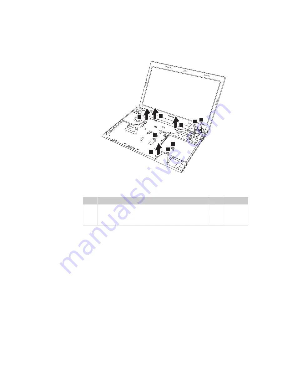
Z570:
Remove five screws
. Unplug four microphone connectors in the
direction shown by arrow
.
When installing:
Make sure that all the connectors are attached firmly.
Step
Screw (quantity)
Color Torque
Z370: M2 × 3 mm, flat-head, nylok-coated (3)
Z470: M2.5 × 5 mm, flat-head, nylok-coated (3)
Z570: M2 × 7 mm, flat-head, nylok-coated (5)
Black
Black
Black
2.5 kgfcm
2.5 kgfcm
3.0 kgfcm
a
b
1
1
1
1
1
2
2
2
2
a
Summary of Contents for IDEAPAD Z370
Page 1: ...Lenovo Z370 Z470 Z570 Hardware Maintenance Manual ...
Page 72: ...Lenovo Z370 Z470 Z570 Hardware Maintenance Manual 68 Z470 Loosen six screws b 2 2 2 2 2 2 ...
Page 73: ...Lenovo Z370 Z470 Z570 69 Z570 Loosen five screws b 2 2 2 2 2 ...
Page 76: ...Lenovo Z370 Z470 Z570 Hardware Maintenance Manual 72 Z470 a b 1 2 2 ...


